Picks and Clicks: Conquer Problem Drawings

This article originally appeared in the February 2011  issue of Professional Surveyor magazine.

While working with IntelliCAD, AutoCAD, or any other AutoCAD-based programs, we’ve all encountered the proverbial drawing from “you-know-where” that seems to drive us crazy from start to finish. Here I offer several tips to help you identify problems and conquer your problem drawings. I’ve listed these tips in the order I would apply them.
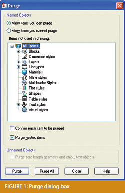
1 Purge your drawing.

The PURGE command removes any unused layers, linetypes, text styles, shapes (for linetypes and text), and many other items in the drawing.

When you run the purge command once, it will purge those items that are not currently in use and that have no other dependencies. For example, if a particular linetype definition depends on a particular shape, the purge command will delete the linetype definition only on the first pass.

Purging again will now delete the shape because the dependent linetype no longer resides in the drawing. Enabling the option to “Purge nested items” before purging will automatically execute the command repeatedly until all unused and dependent items are gone.

2 Purge remnants of registered applications that have accessed your drawing.

Typing “–PURGE” will execute the command line version of the purge command. This version includes a few options not available from the purge dialog box.

One of the extra options is “Regapps,” which is available only from the command line version of the command. You access it by typing “R” when prompted. This option removes “leftover” data from other programs (registered applications) that have been used to work on the drawing file.

3 Audit the drawing.

The AUDIT command looks for discrepancies between the objects displayed on the screen and the objects’ definitions in the drawing file database. The command then gives you the option of correcting the errors it has found. This command can be executed only while the drawing is open and active.

4 Recover the drawing and all reference files.

The RECOVER command is a more robust version of the audit command and can be used to open drawings that are so corrupt they cannot be opened otherwise.

Starting the recover command prompts you to browse to and select the problem drawing. If the problem drawing is already open and active, recover will prompt you to save changes before reopening the drawing and starting the recovery process.

For drawings that have attached XREFs (external references), use the RECOVERALL command to open and repair the selected drawing plus all dependent XREFs. Note that errors corrected by the audit are not saved back to the XREFs.
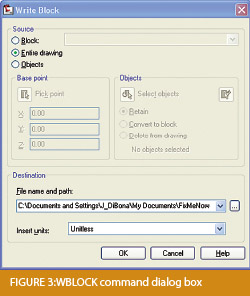
5 Block out the drawing contents to a new drawing.

If you suspect a drawing has become corrupt, you can WBLOCK the entire drawing out to another file. After starting the wblock command, set the “Source” option as “Entire Drawing” and provide the location and name for the newly created file.

Note that this command saves only Model Space entities to the new drawing. If needed, use AutoCAD Design Center to transfer layout tabs.

6 Insert the problem drawing as a block into a new drawing.

Using the same principle as above, you can use the INSERT command to bring the Model Space contents of a problem drawing into another drawing. Doing this will reduce or eliminate corruption in the problem drawing.

Make sure to use 0,0,0 as the insertion point and set the rotation angle and scale appropriately.

As with wblock, this command saves only Model Space entities to the new drawing. If needed, use AutoCAD Design Center to transfer Layout tabs.

7 Export drawings from vertical programs to AutoCAD.

Autodesk products such as Land Desktop or Civil 3D create program-specific, proprietary entities such as AEC Contours and AEC Point Objects. These proprietary objects can become corrupt or otherwise create problems when being accessed from standard AutoCAD or another program that doesn’t recognize the proprietary entities.

You can enter the -EXPORTTOAUTOCAD command at the command line to create a new drawing file that strips out the proprietary entities and leaves only standard AutoCAD entities. For instance, a Land Desktop or Civil 3D drawing containing AEC Contour entities will result in elevated polylines with text when exported to Autocad. And a Land Desktop or Civil 3D drawing containing AEC Point entities will result in a block with attributes when exported to AutoCAD.

Note that any AEC Objects will obviously lose their intelligence, but the new drawing can be opened in any version of Autocad.
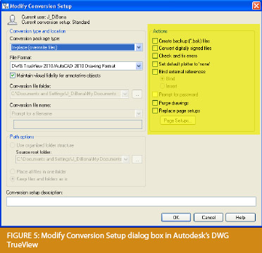
8 Use DWG TrueView Convert to fix errors and bind XREFs.

DWG TrueView is a free program that you can download from Autodesk’s website. It is most valuable for its ability to convert drawings to earlier versions individually or in bulk. In the Conversion Setup dialog box, you can specify one or more options to clean drawings during the conversion process.
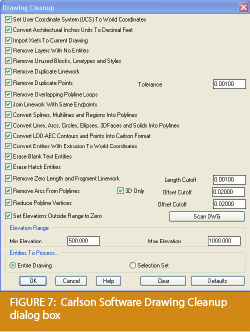
9 Use the Drawing Cleanup command in AutoCAD Map or Carlson Software.
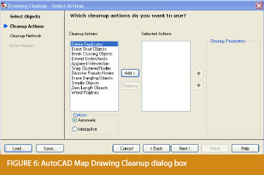
Both AutoCAD Map and Carlson Software provide Drawing Cleanup commands that provide a variety of cleanup tools. In either version, you have the option of performing one or more cleanup tasks on the entire drawing or on only selected entities in the drawing.

Note: Use these commands with caution and apply cleanup options incrementally to avoid making unwanted changes. Also, I recommend making a backup copy of the active drawing before performing this command.

If you use AutoCAD Map, Land Desktop, or Civil 3D, you can access the Drawing Cleanup command from Map ➜ Tools. In Carlson Software, access it from the File menu.

10

I’ve come up with 9 tips that will help you clean up and, maybe, access drawings that have become corrupt. To round out the list and make it an even 10, I’d like to hear from readers to find out what your favorite drawing recovery and cleanup tools are. Please email me at ContactUs@thatcadgirl.com and I’ll report in a future column.

This article originally appeared in the February 2011 issue of Professional Surveyor magazine.


Picks and Clicks: Dynamic Blocks

This article originally appeared in the December 2010  issue of Professional Surveyor magazine.

Welcome to the first installment of this new column highlighting favorite AutoDesk, IntelliCAD, and Carlson Software features. My goal is to help you reduce your number of  “picks and clicks” while using these pieces of software so you can be more efficient, saving time and money.

Because many of us are hanging onto our current software versions for as long as possible these days, I will try to avoid reviewing features that were released in “last week’s” version and will instead write about commands and features that have been around for at least a few years.

First: A little about my background and experience. My first CAD class was with AutoCAD 9 and DCA software as part of my Surveying Technology coursework in college. After graduating, I worked for various consulting, engineering, and surveying companies where I used mostly the Autodesk family of products: AutoCAD, AutoCAD Map, Land Desktop, and Civil Design with brief detours into the MicroStation, GeoPak and Eagle Point worlds.

It was during this time that I started teaching basic CAD and civil/survey CAD classes at local community colleges. I then joined a local Autodesk and Carlson Software reseller to help start and build their training division. In 2004 I stepped out to begin working for myself as That CAD Girl. I offer Carlson Software sales; training and support for Autodesk, Carlson and IntelliCAD; and associated consulting services while specializing in CAD standards development and surface modeling training. My website is at www.thatcadgirl.com. And my surveying column is now here!


Water Valve

(Figure A)

One of my favorite, fairly new AutoCAD features is Dynamic Blocks, which was first introduced in AutoCAD 2006. A Dynamic Block is simply a standard block that has been enhanced with additional functionality. You may have seen examples of complex Dynamic Blocks that allow you to change the size (by stretching) or the orientation (by mirroring) only pieces of a block without having to EXPLODE it. But, you can also save many picks and clicks by giving your existing blocks a facelift with some simple Dynamic functionality. Let’s start with a standard symbol or block that most everyone will already have saved in a block library somewhere: a Water Valve.

To use the standard version of this block in a drawing, we usually have to:

  1. Use the INSERT command to bring the block into the drawing.
  2. Use a NEArest OSNAP to position the block on a line representing a waterline.
  3. Use the ROTATE command with the Reference option to align the block with the line.
  4. Whew!

Two minutes (or less) in the Block Editor will eliminate steps 2-4 (at right.)

  1. Insert the standard Water Valve block into your current drawing.
  2. Left-click to select the block.
  3. Right-click and open the Block Editor from the shortcut menu.
  4. On the “Parameters” tab of the Block Authoring Palette, select the tool to create an Alignment Parameter. [Figure B]
  5. The Command: line prompts you to, “Specify base point of alignment or [Name]:”. Use your INTersection OSNAP to specify the insertion point for the block.

  6. Next, you are prompted to “Specify alignment direction or alignment type [Type] <Type>:”.  [Figure C]  Turn Ortho On and pick a point directly to the right of the insertion point.

  7. When finished, the block with its new Alignment icon will look like this in the Block Editor: [Figure D]
  8. 
Pick the Close Block Editor button at the top of the screen and then pick “Yes” when prompted to save the block definition.


Using the Dynamic Block

Once you are back in the main drawing screen, the original instance of the block will have been updated.

  1. Left-click the block to see the new Alignment icon.
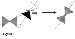
  2. Left-click on the blue Alignment icon. This allows you to “pick up” the block and move it. [Figure E]
  3. Drag the block on top of a line in your drawing that represents a waterline. You will notice that, once your crosshairs are positioned over the line, the block automatically aligns itself to the line, and, in addition, the NEArest OSNAP is enabled allowing you to position and snap the block directly onto the line.
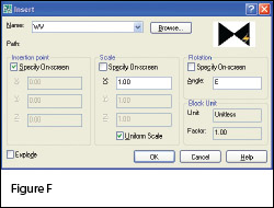
  4. Use the Insert command to draw additional copies of the block into the drawing. Notice that the thumbnail image of blocks with Dynamic parameters displays a lightning bolt icon so as to differentiate Dynamic Blocks from standard blocks. [Figure F]

Waterline Reducer

[Figure G]

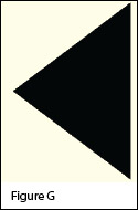
Another often-used water-utility symbol that can benefit from the addition of Dynamic properties is the waterline Reducer. This symbol is used to indicate a change in the size of a waterline. In addition to an Alignment Parameter, this symbol needs a Flip Parameter that allows us to easily mirror it to change its direction. Unlike an Alignment Parameter, adding a Flip Parameter to a block also requires that you add a second Dynamic Block component called an Action. Giving a block “flip-ability” requires a few more steps, but is still rather easy.

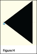
  1. Repeat steps 1-7 as described for the Water Valve to insert the “Reducer” block into the drawing and add an Alignment Parameter to it. The Reducer with its Alignment icon is shown at left: [Figure H]
  2. Turn Ortho On.
  3. Pick the Flip Parameter icon on the Block Authoring Palette. [Figure I]
  4. The Command: line prompts you to “Specify base point of reflection line or [Name/Label/Description/Palette]:”. Use your ENDPoint OSNAP to specify the insertion point for the block (use the same point as for the Alignment Parameter).
  5. The Command: line next prompts you to “Specify endpoint of reflection line:”. With Ortho On, pick a point directly above the “Base Point” specified in the previous step. These two points define the “reflection line” for mirroring.
  6. You are then prompted to “Specify label location:”. Pick a point somewhere just above the Reducer symbol. The label reads, “Flip state”.
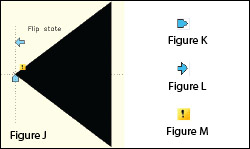
  7. Use the MOVE command, with Ortho On, to slide the Flip icon above the block.
  8. The Reducer [Figure J] with its Alignment  [Figure K] and Flip icons  [Figure L]  are shown at right. A Warning icon [Figure M] is also displayed indicating a missing Action component.
  9. On the “Actions” tab of the Block Authoring Palette, select the tool to create a Flip Action. [Figure N]
  10. The Command: line prompts you to “Select Parameter:”. Select any part of the Flip Parameter including the label, the Flip icon, or the Warning icon.
  11. Next, you are prompted to “Specify selection set for action. Select Objects:”. Select the Flip icon and all entities that make up the block/symbol.
  12. You are then prompted to “Specify action location:”. Pick a point somewhere near the “Flip state” label. The label has a lightning bolt icon and reads, “Flip”.
  13. Pick the Close Block Editor button at the top of the screen and then pick “Yes” when prompted to save the block definition.

Using the Dynamic Block

As before, once you are back in the main drawing screen, the original instance of the block will have been updated.
  1. Left-click the block to seea the new Alignment and Flip icons.
  2. Left-click on the blue Alignment icon to move it onto a line representing a waterline.
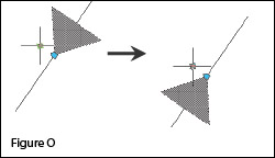
  3. Left-click on the blue Flip icon to mirror the block along the line.
  4. Use the Insert command to draw additional copies of the block into the drawing. [Figure O]

Note that the steps change the block definition in the current drawing only. The WBLOCK command must be used to save the block out as an external Drawing (.dwg) file.

This article originally appeared in the December 2010 issue of Professional Surveyor magazine.


What is Carlson up to?

This is a good article about Bruce Carlson and where Carlson Software is planning to go in the future…

Independence All the Way

Originally posted on Carlson Connection by Jennifer Dibona


The Kansas City Carlson User Group

I’m reflecting on my impressions of the inaugural meeting of the Kansas City Carlson User Group meeting held at the corporate office of Griner & Schmitz on August 20, 2009. About a dozen individuals showed up to form new business relationships with one another and draw on the strengths from their common bond.

The meeting started out with the gracious hospitality of Griner & Schmitz who hosted the event at their corporate headquarters in Kansas City. Complimentary food and beverages were aplenty and the guests quickly found themselves forming or renewing friendships with others in attendance.

After a bit of socializing, the guests were treated to a sneak peek of Carlson SurvCE 2.5 from Carlson Software South Central Regional Sales Director Aaron Newman. Aaron demonstrated many of the new and powerful features of SurvCE and showed the attendees how to leverage the power of the Carlson Field-to-Finish routines. Throughout the presentation, one of the key benefits of a User Group is that questions posed by one individual benefits the others and attendees are generally willing to share their observations and experiences with others. After Aaron’s presentation, I was given the opportunity to demonstrate some of the new features that will be released with Carlson 2010 with particular focus on surveying and the communication of information between the field and the office.

It was amazing at how quickly the two-hour meeting flew by but it is my opinion the Kansas City Carlson User Group is off to a great start. If you’re in the Kansas City area in mid-October for the expected follow-up meeting, consider dropping in for some informational aspects of the products and services offered by Carlson Software. Otherwise, express your interest in forming a Carlson User Group in your region!

Originally posted on Carlson Connection by Ladd Nelson


BIM is not GIS

As someone quite entrenched in both disciplines (Civil and Architectural), I’ll add my 2 cents worth on the BIM vs. GIS subject.

In my opinion, BIM and GIS are both “methodologies” rather than “products”. The acronyms each have their own meaning and refer to designing, building, and managing information in a full life-cycle.

Each discipline has its own standards; from CAD standards to design standards (think of AIA vs. AASHTO), but both BIM and GIS rely on correct As-Built data to provide accurate information about their models.

BIM
The National BIM standard states the definition of BIM as:

BIM is best thought of as a digital representation of physical and functional characteristics of a facility…and a shared knowledge resource for information about a facility forming a reliable basis for decisions during its life-cycle; defined as existing from earliest conception to demolition.”

Autodesk has taken the BIM acronym that has provided a great deal of success with their Architectural Modelling packages and applied it to their Civil products as well. Their logic appears to be that its a “3D” product, therefore it is a “BIM” product. I believe that it is irresponsible to change terminology to simply advance product sales.

On the Autodesk Web Site, Autodesk lists a number of products as being “BIM” products:

  • Revit
  • Navisworks
  • Design Review
  • AutoCAD LT
  • + several more

With the acronym meaning Building Information Modelling (with building being a verb OR a noun), its interesting to see products such as AutoCAD LT and Design Review being shown on the list.

Revit
Revit is a Design Tool that allows the storage of certain pieces of information as well as the ability to add custom fields (heating capacity, cooling capacity, etc.) to the actual objects.

Navisworks
Navisworks integrates information from multiple data sources to provide a cohesive collection of information (graphics and data) to analyze things such as clash detection (HVAC duct work clashing with structural components, etc.).

AutoCAD LT
AutoCAD LT is Autodesk’s low-end design package. Apparently, any DWG file creation tool is now a BIM product as well.

Design Review
Design Review is a light-weight DWF viewer and markup tool. While it has been used as a backbone of products such as FMDesktop, its neither a Design tool, nor a Modelling tool.

FMDesktop
Absent from the list is FMDesktop. FMDesktop was one of Autodesk’s tools for managing the Building Information and Autodesk just dropped the product (Note: There are dozens of Facilities Managent Products available that provide similar capabilities such as FM:Systems, Archibus, Tririga, Manhattan, Cadapult, Famis, and more).

In the 2006 – 2007 time frame (when Autodesk acquired FMDesktop), Autodesk themselves showed customers Power Point slides regarding BIM. These slides showed where the “Design”, “Build”, and then “Operate and Manage” processes were performed. FMDesktop was Autodesk’s solution to tell the story of the building lifecycle and where the information was to be managed. These were broken down into 2 sections: The “Data Collection” piece and the FMDesktop piece.

Data Collection incorporated the Design (several disciplines such as Architects, MEP Systems Engineers, and Structural Engineers) as well as the majority of the Build process. The FMDesktop piece overlapped the Build process and then took over for the “Operate and Manage” process.

In my opinion, building that model of information AND managing that information is the true test of a “BIM” solution. There is no 1 product that is a “BIM” product. Its a series of technologies that are incorporated to provide the “information”.

Ultimately, a database component is required to work with the graphical representation of data (which certainly could be referred to as the “Building Model”).

GIS
GIS is BIM’s counterpart whereby Geographic (position on the planet) information is being stored and managed.

Most end users might think of GIS solutions as Google Maps or Google Earth where they can enter an address and out pops a graphic representation of that location or directions on how to get there. The graphic is just the tip of the iceberg. Without the data, the graphic would simply be a pretty picture.

Just as with BIM data, GIS data utilizes design tools to build the graphics and As-Built data and then tools to expand upon the As-Built information.

While there are a number of individual products on the market to assist in the creation, manipulation and distribution of GIS data, a complete GIS system involves more than 1 product or techonology.

A couple of the common Design Products are: Autodesk Civil 3D and Carlson Civil Suite

AutoCAD Civil 3D
Civil 3D is an object-oriented design tool for Civil Engineering applications. Because the tool is object oriented, the end product is not easily distributable. The data can be transferred to other links in the GIS solution chain by using technologies such as LandXML, but the graphical interaction is lost in this process (i.e. the objects are lost).

Carlson Civil Suite
Carlson’s Civil products work with DWG files in an AutoCAD or IntelliCAD DWG format. Because the data is stored as compatible DWG information with external data files, the data is easily transferred to other products in the GIS solution chain.

Managing the data developed in the design process is the next component of the GIS life-cycle. A number of products provide those solutions: ESRI ArcGIS, Vueworks, and Custom Mapguide Solutions.

ESRI ArcGIS
ESRI’s shp (shape) and adn (coverage) files are quite possibly the most prevalent GIS specific data files available and are often integrated in GIS solutions. ArcGIS allows GIS solutions to be deployed similar to FM solutions in the BIM world.

Vueworks
Vueworks is an organization that builds GIS and Work Management solutions using the ESRI base applications.

MapGuide
MapGuide is Autodesk’s development environment to build GIS applications. It is often used in concert with ESRI, Microstation and Autodesk data files.

GIS Standard
While there is not yet a concensus on a singular GIS standard, there are independent Spatial Data Standards employed by each digester of GIS data. You can view some of those here:

Both GIS and BIM perform very specific functions in accordance with their own disciplines. While the terminology is often mis-used, they refer to unique information systems; BIM in the structural facility world and GIS in the geographic world.

Originally posted on Carlson Connection by Jon Luby


Carlson Webinars – BIM, GIS and CAD Standards

Carlson Software recently asked Felicia and me to present webinars on topics we have particular interest in or specialize in. 

Felicia’s webinar on BIM, GIS and Carlson Software can be viewed here: BIM, GIS and Carlson Software Webinar

My webinar on CAD Standards can be viewed here: CAD Standards for Carlson Software with AutoCAD or IntelliCAD

Originally posted on Carlson Connection by Jennifer Dibona


Carlson 2010 Sneak Peek

The 2010 edition of Carlson Software is a few weeks away from general release and is slated to have approximately 400 new features and enhancements. Suffice it to say, there should be something for just about everyone with this release. While by no means exhaustive, here are just a few of the new features that will be found in Carlson 2010 (a few of which were mentioned in the Coming in Carlson 2010 post):

  1. Support for IntelliCAD 6.6 and the AutoCAD 2010 product line – Carlson 2010 will continue to ship with a complimentary copy of IntelliCAD now based on the 6.6 code stream from the IntelliCAD Technology Consortium. Work continues on the migration to the IntelliCAD 7 release which is expected later this year or early in 2010. Carlson 2010 will also support the AutoCAD 2010 family of products including AutoCAD, AutoCAD Map, et. al. Since Land Desktop was officially retired in summer, 2008, now is a great time for organizations to look at Carlson as an alternative to the Land Desktop upgrade path.

    Side note observation… For those Carlson IntelliCAD users out there, don’t forget to inquire about your complimentary Carlson-IntelliCAD GIS Starter Kit from ESRI!

  2. Settings Explorer for CAD Managers – Carlson 2010 introduces an efficient Settings Explorer that allows CAD Managers and users alike to examine, set and migrate settings from machine to machine within an organization.
  3. Layout Manager and Field Text for CAD Drafters – Geared for deliverable output, the Layout Manager and Field Text routines helps automate the creation of plot-ready maps.
  4. Smart Annotation for CAD Drafters and Surveyors – Carlson 2010 helps simplify the annotation typically applied to subdivisions.
  5. Merging of C&G into Carlson Survey for Surveyors – The long-awaited integration of Carlson’s C&G product line with the more traditional Carlson Survey routines provides land surveyors with arguably the most comprehensive collection of survey routines available today.
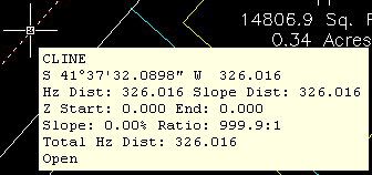
  6. Drawing Inspector Multi-select for everyone – The highly useful Carlson Drawing Inspector is becoming even more useful with the ability to now display multiple information categories at once.
    Multi-option Drawing Inspector
    Multi-option Drawing Inspector
  7. Template Grade Table for Engineers – In an effort to augment the highly flexible and powerful Template Transition, Template Point Centerline and Template Point Profile routines found in Carlson Civil, a new Template Grade Table provides robust functionality that can be used to design a variety of roadway scenarios. Additionally, the information found in the Template Grade Table can also be utilized in Carlson SurvCE beginning with the 2.5 version of the product.
  8. Edge of Pavement Profiles for Engineers – The ability to produce the graphical results of edge of pavement profiles is now much simpler with Carlson 2010 by giving engineers the ability to extract profile information from the imperical design values that contribute to the vertical aspect of the roadway design.
  9. HydroCAD Linkage for Hydrologists – As originally announced at the 1st annual Carlson User Conference, the data collaboration between Carlson Hydrology and HydroCAD will help users “save time on repetitious data entry, increasing their accuracy, and giving them access to HydroCAD’s extensive rainfall libraries and stormwater chamber specifications.”
  10. Improved Watershed Delineation for Hydrologists – Watersheds in Carlson 2010 can be delineated by three levels: drainage, land use and soil type.

For Carlson Mining clients that might also happen to come across this post, Carlson 2010 offers new functionality for you, too! Check with your Carlson Mining specialist for additional details.

To summarize, Carlson Software is continuing to offer responsive solutions to client-requested technology needs and is standing ready to assist you! Check out our wide-array of technolgy solutions by visiting us on-line at http://www.carlsonsw.com!

Originally posted on Carlson Connection by Ladd Nelson


Online Training – Friend or Foe?

With the economy what it is and everyone trying to get as much bang for their buck as possible, I’m finding that online training for your CAD software programs is an increasingly popular and cost effective option.

Although this post describes my personal approach and may be different considering your trainer, hopefully it will answer some of your questions about online training and will encourage you to give it a try.

How does it work?
There are several online services that trainers may use for online training. WebEx, GoToMeeting and GoToWebinar are all very commonly used and popular. My preference is GoToMeeting and GoToWebinar as they have a very low footprint on your computer and are simple to use. When first entering an online meeting, a small installation of the program occurs allowing you to view and interact with the presenter’s computer.

GoToMeeting is smaller scale and better for personalized training. GoToWebinar can handle up to 1,000 “attendees” and is typically used for presentation or demonstration to a large group.

Some of the online meeting services are free, but most require a monthly fee. The fee is paid by the organizer who then has the ability to schedule meetings/webinars in advance or “Meet Now” for meetings on the fly. Your organizer will either email you a link to the meeting site or can tell you the link on the phone. Each meeting has a unique “Meeting ID” that you’ll enter at the main page.

GoToMeeting is typically used for standard training where more than one person may need to show their screen and/or be given control of the mouse and keyboard. This interaction can take place in a variety of ways. When in a meeting, anyone can be given (and must accept) the “Presenter” role which allows others to view their computer. And, even though the Presenter always has priority, control of the mouse movement and keyboard entry may be granted to others in the meeting. This allows someone else to work on my computer remotely.

The audio portion of the training usually takes place by calling in on a conference call line supplied by GoToMeeting. VOIP (Voice Over Internet Protocol) is also available allowing you to use your computer’s speakers and microphone but it is not recommended because of quality.

GoToWebinar is used for larger scale demonstration and presentations and can accommodate up to 1,000 Attendees. Online Webinars are generally structured to have one or more Presenters making the presentation.

Like GoToMeeting, the audio portion of GoToWebinar usually takes place by calling in on a conference call line supplied by GoToWebinar. However, in a Webinar setting, the Attendees are muted automatically by the Presenter so that everyone isn’t blessed with the sound of crinkling potato chip bags and elevator music when someone puts the phone on hold. The Presenter has the ability to un-mute one or more Attendees as needed. The audio of all Attendees is managed by the Presenter by having each Attendee enter a unique “Audio PIN” upon arrival.

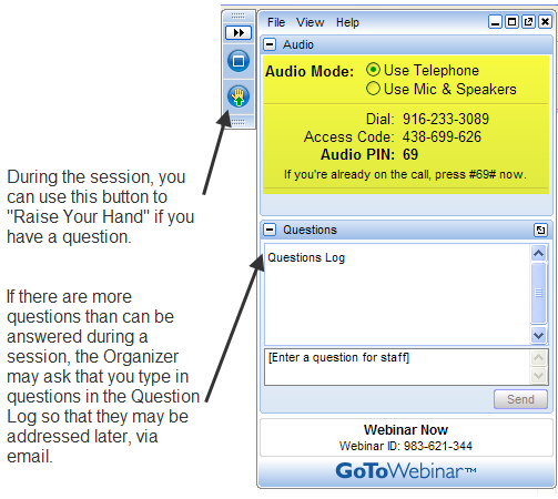
GoToWebinar has 2 ways to ask and respond to questions from Attendees. The Control Panel has a “Raise Your Hand” button that notifies the Presenter there is a question. Depending on time constraints, the Presenter may decide to un-mute and answer the question during the online session.  If there are more questions than can be answered during a session, the Organizer may ask that you type in questions in the “Questions Log” so that they may be addressed at a later time.

GoToWebinar_ControlPanel2

Pros and Cons 
I’ve put together what I consider to be the Pros and Cons of online training for CAD Software programs. Please pitch in and offer your comments.

Pros

  • Can eliminate travel time and expenses
  • Very cost effective option for customized one-on-one training
  • Allows for personalized, absolutely customized training because it’s normally one on one.
  • Can’t find a local trainer? No problem. Felicia Provencal can train you from Hawai’i – although you may want to go to her!
  • Can be set up within minutes if there is a pressing technical support issue or project that suddenly comes up.
  • Can be scheduled in shorter blocks of time – one of the best ways to make sure you retain what you are taught. I like to schedule 2 hours maximum per session.
  • Shorter blocks of time allow for easy customization of training topics from one session to the next. If more time is needed on certain features, it’s easy to squeeze in another 2 hour session.
  • It IS interactive!
  • All sessions can be recorded and played back at your convenience for a refresher.

Cons

  • Some people are more comfortable sitting beside and working directly with the trainer
  • It’s less interactive than hands-on, in person training.
  • For hands on training and depending on the material being covered, it may not work as well if you have several folks needing training at one time.
  • Requires a high-speed connection and a telephone headset allowing two hands on keyboard. A speakerphone can be used as long as feedback doesn’t become an issue.

Real World Example
I recently worked with a client from out of state. He is a grading contractor who thought he needed Carlson TakeOff training but, after some discussion, realized training in basic CAD (IntelliCAD) needed to come first and then TakeOff training.

The initial proposal was for me to travel there and spend 3-4 days training this client plus a second person (a competitor, in this case) who needed the same training. Both of them decided to give online training a try.

We scheduled online training for every morning one week. I worked with one from 7:30 – 9:30 am and then with the other from 10:30 – 12:30 pm. After the 3rd day, we had covered so much material that one asked to skip the next day so he could work with it himself and apply what he’d learned so far.

We ended up skipping two days. By the time we met again, he’d worked with it enough and become so much more proficient with the basic CAD operation that we were able to fast-forward through the next couple sessions and started working on his current project. Another subsequent session was cancelled because the rain finally stopped!

And then a few days later, he needed to get his project finished and out to bid. So, after our first session one morning, we set up another session at 4:00 that afternoon and worked until almost 7:00 that evening.

Both customers ended up very happy with the amount of material we covered and where they were with the software when we wrapped up our regular training. They still have the video recordings of the training for their reference to go back to when needed. In the end, the cost was almost the exact same as it would have been had I fulfilled the original proposal but they both learned and retained much more because the training was customized and personalized to their specific jobs.

Originally posted on Carlson Connection by Jennifer Dibona


Carlson-IntelliCAD GIS Starter Kit from ESRI

Those currently using Carlson with IntelliCAD are eligible for a new “GIS Starter Kit” from ESRI. The Kit includes:

  • ArcGIS ArcView desktop software
  • A copy of the book A to Z GIS: An Illustrated Dictionary of Geographic Information Systems
  • A copy of GIS Tutorial: Workbook for ArcView 9, Third Edition
  • A 10% discount for the ESRI Survey & Engineering GIS Summit ($325 – standard registration price)

To take advantage of the offer, call 1-800-GIS-XPRT (1-800-447-9778) and request the Carlson-IntelliCAD GIS Starter Kit and please have your Carlson Serial Number available.

You can read more about ESRI’s commitment to survey and engineering services by visiting http://www.ESRI.com/engineering.

Originally posted on Carlson Connection by Jennifer DiBona


A Closer Look at the Drawing Inspector

There are times when you need to know information about an object in your drawing such as its layer, elevation, or direction and distance.  The Drawing Inspector provides a quick and easy way to gather information about drawing entities on the fly.  Simply turn on the Drawing Inspector using the Inquiry pull-down menu, then hover your mouse over any entity.  Soon the information you require will be displayed in a tooltip next to your mouse location.

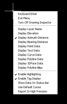
This command is available in any of the Civil Suite products (Survey, Civil, Hydrology, and GIS), or Takeoff.  It works in both software installed on the AutoCAD platform or the IntelliCAD platform.  By default, it will display the layer an object resides upon in the tooltip, but you can change the type of information shown using the right-click context menu.

The right-click context menu displays the options for the Drawing Inspector

When you are finished viewing information about your drawing objects, right-click and choose the Turn Off Drawing Inspector option.  You can also toggle the Drawing Inspector off using the Inquiry pull-down menu.
Originally posted on Carlson Connection by Felicia Provencal

1 of 1