Carlson Tip of the Day… List of improvements in Carlson 2015 programs

carlson2015splash


General

  • AutoCAD 2015 – Added support for this new version.
  • IntelliCAD 8.0 – Direct support for 2013 DWG file format. Added 64-bit version. New features including support for dynamic entity reactors, layer states and  improved ddvpoint interface.
  • Google Earth – Added support for exporting 3D Faces.
  • Import 3D View Model File – New command to create drawing entities from a 3D model file.
  • Export 3D View Model File – New command to create a 3D model file from selected drawing entities.
  • 3D Model Library – New command to prepare the 3D models to use in the 3D Viewer commands.
  • Toolbar Manager – New command to save status of toolbars and allow migrating toolbar settings between versions.
  • File Selection – Added list of subfolders within current folder and button to move up a folder level. Added option for warning when selecting a data file that is not within the current project folders.
  • Textures – Added 40 new textures for 3D viewing.
  • Settings File Manager – Added function to compare two settings files and report differences.
  • Leader With Text – Added option for horizontal tick and option to create with Mtext.
  • Join Nearest – Added filters for common colors and linetypes.
  • Join Polyline By Trace – New command to join linework into a polyline with prompts at intersections


Survey Commands

  • Field To Finish – Added special pipe feature coding with ability to create pipe network (.sew) file. For tree feature coding, added option for drip as diameter instead of radius, added option for solid circle for trunk and option for relative tree size for the symbols. Added control for separate layers for the point attribute block and point node. Added new AFIT special code for making a curve tangent through a series of three curve points. Added method for dynamic templates with variable horizontal and vertical offsets by using the OH and OV special codes. Added settings file default distinct point layer prefix/suffix. Added separate text size settings for attribute text labels and point block attributes.
  • SurvNET – Added error report for individiaul observations to track down blunders. Added import for TDS GPS vectors.
  • Edit Process Level Data – Added support for processing with zero horizontal distances.
  • Carlson Cloud – New command for communicating with SurvCE for sending messages, data files and crew locations.
  • Report Distance Scale – Added methods for grid/ground factors on-the-fly in addition to a fixed factor.
  • 3D Transformations – Added 3D coordinate transformations.
  • Point Group Manager – Added method to create point group by offset distance from alignment polyline.
  • Move Point Attributes With Leader – Added controls for attribute order and ability for curved leaders.
  • Import Text/ASCII File – Added method import from text with fixed widths and method to use inclusion/exclusion perimeters.
  • Legal Description – Added method to report station/offset using a reference centerline. Added method for reporting with geodetic mean angle and geodetic distances.
  • Cut Sheet – Added method to get station/offset from the point description coding. Added field for design point description.
  • Offset Points By Interval – New command to create offset points along an alignment.
  • Label Coordinates – Added options to include a description, to use Mtext, to draw the labels at an angle and option for mleader.
  • Draw Legend – Added method to put each symbol or a specific layer.


Civil Commands

  • Draw Profile – For paper space profiles, added method to use an existing layout as a reference template for the new layout. For the horizontal label box, added option for horizontal text in addition to vertical. For pipe profiles, added settings to label inverts by left/right order, added option to draw cutoff style pipe extensions, added option to create labels as MText, added option for flow arrow in middle of pipe, new option for labels above the pipes, added justification settings per label, added setting for separate layer for pipe thickness than pipe profile and option to connect rims with a polyline for a simple surface profile. For Label Line/Point crossings, added option to label elevations at crossings, added method for labeling GIS attributes, added method to label points of selected descriptions within offset tolerance, added option to label CL deflections and added option to avoid label overlaps. Added special CL stations for break point station/elevation labels plus new prefix/suffix settings. For EOP profiles, added new break point and EOP leader style to the start of the labels, added option to label ground profile on road EOP profiles and added controls to select which profiles are EOP, road and ground. For the manhole name within circle option, added setting to put the name and number on separate lines and added the option to auto shift the labels to avoid overlaps.
  • Draw Sections – Added option to label cut/fill volumes per station. Added separate settings for pipe crossing layers for decimals on pipe size, offset and elevation.
  • Draw Plan View Sheets – Added option to set station range to draw.
  • Input-Edit Centerline – Added Fit Curve method to apply speed table to all PIs in centerline.
  • Input-Edit Profile – Added method to apply speed table for vertical curve lengths to all PIs in profile.
  • Label Station/Offset – Added method to use a TIN or grid surface for the elevation reference.
  • Draw Lot Setback – Added method for separate corner side setback amount.
  • Move Spot Elevations – New command to move spot labels and update elevation to new position on reference surface.
  • Line Of Sight Viewshed – New command to calculate line-of-sight from a point and eye height on a surface.
  • Draw Spot Elevations – Added option for label only and option to pick an entity instead of a point.
  • Cut/Fill Labels – For points method, added more options like separate layers for existing and design. For the TIN method, added options for deep cut/fill labels and option for marker symbol.
  • Smooth Polylines – Added method to smooth polyline between selected points.
  • Triangulation File Utilities – Added function to color TIN within inclusion perimeter.
  • Road Stripe Library – New command to setup named sets of road stripes with offsets, colors and styles.
  • Draw Road Stripes – New command to draw linework for road stripes.
  • Linear 3D Object Polylines – New set of commands to manage alignment polylines for 3D Viewer commands for linear 3D features such as fences or guard rails.
  • Label Profile On Centerline – Added label position by left/right in addition to above/below. Added prefix/suffix and station interval settings.
  • Offset 3D Polyline By Grade Table – New command to offset a 3D polyline using the distances and slopes from a template grade table.
  • Road Network – Added settings for station range to process for each road.
  • Mass Haul Analysis – For borrow pits, added offset from road to account for offset travel time.
  • Sections From 3D Polylines – New command to create cross sections from 3D polylines.
  • Surface 3D Viewer – Added option to show contours. Added functions to edit triangulation by swapping edges, adding breaklines, removing points, removing triangles or editing point elevations.
  • Surface 3D Flyover – Surface model is kept in sync with any edits in CAD so that the 3D view is automatically updated. Added method to add models to the scene by screen picking plus the ability to pick models in the scene to edit properties (location, rotation, scale). Added function to record a movie. Added method to map textures by color and method to scale textures. Added run view mode for detached from moving vehicle. Added option to show contours. In pick mode, display real-time coordinate and elevation for mouse position on surface.
  • Motion 3D Viewer – New command to assign path polylines with speeds to 3D models and the camera.


Hydrology Commands

  • Design Detention Pond – New command with all steps for detention pond design plus support for multiple rain events.
  • Pipe Culvert Design – Added method for tailwater by channel or discharge rating and added overtopping analysis.
  • SCS Rainfall Library – New command to define an SCS data reference library for rain events.
  • Rational Rainfall Library – Added import of IDF tables from comma separated text files.
  • Collision Conflict Check – Added support for checking unlimited pipe networks and using the report formatter.
  • Sewer Network Design – Added option for junction loss for pipe connections including laterals. Added method for tailwater at each outlet. New method to set symbol rotation by screen pick. Added graphic preview during .sew file selection.
  • Lateral Design – Allow for multiple lateral connections at manholes.
  • Identify Pipe Polylines – New command to ID or list pipe data assigned to 3D polylines.
  • Import Network From 3D Polylines – Added method to control order of names by design order, elevation or polyline direction. Added method to set rim elevation by depth.


GIS Commands

  • Label GIS Point Data – New command to create text labels or block with attributes for selected GIS attributes.


Field Commands

  • Drivers: Upgraded many drivers from the SurvCE updates.


Geology Commands

  • Define Mining Model – Added Mine Model collection of surfaces for modeling only mineable strata already adjusted for recovery, roof/floor gain/loss and minimum parting. Renamed “Pre-Calc Model” to “Geologic Model”.
  • Geologic To Mining Model – New command to adjust a Geologic Model to make a Mining Model.
  • Drillhole Database – Added support for MS Access .accdb format.
  • DHDB – Added drillhole database import/export to DHDB format.
  • Import From Coal Section – New command to create pit/channel samples from coal sections.
  • Configure Section Info – Added method to set folder for section drawing to allow storing the section info on a server.
  • Import/Export Coal Sections From Text File – New commands to import/export coal sections from/to text files.
  • Grid Files – Added option to store .grd files as binary to improve read/write speed.
  • Grid File Utilities – Added method to call other GFU macros and pass parameters from another macro. Added sin() and cos() functions for grid math. New dialog interface including dialog for creating IF statements. Added 3D window to show grid while modified.
  • Draw Geologic Column – Added method to draw in  3D with strata sections sized based on grade parameters. Also added 3D draw method as 3D lines. Added method to label grade names and added separate layer settings for attribute labels. For labels in 3D, added options for rotate labels vertical and draw label leaders. 3D Viewer Window now shows 3D text generated by Geologic Column.
  • Drillhole Report – Added method to report grades for each strata.
  • Drillhole Core Images – Added method to draw the report to the drawing and added option for labeling depth or elevation.
  • Draw eLog – New command to draw graph of selected attributes from an eLog LAS file.
  • Create Drillhole from eLog – New command to create drillholes with strata classification using the eLog paramters.
  • Trim Isopach Within Fault Zone – New command to isopach elevations and break contours at fault zones.
  • Draw Fault Labels – New command to label fault deltas.
  • Draw Fault Symbols – New command to draw +/- symbols for faults.
  • Apply Faults To Grid – Added method to handle thrust faults. Added method for processing multiple grids at a time.
  • Surface Mine Reserves – Added Adjust Pits Manager for adjusting pit perimeters with real-time quantity updates.
  • Draw Grade Boundary – New command to draw boundary polylines around area with specified grade.
  • Block Model Statistics – Added min/max/average elevation and depth to the report. Added level # to report name.

Surface/Underground Mining Commands

  • Ribbon – Added a mining ribbon for running with AutoCAD 2012 and higher.
  • Import Pit Points – Added method for user-defined input file formats.
  • Import Polyline File – Added method to draw 3D polylines from sequence of top/bottom points for blast holes.
  • Label Property Lines – Added option to label owner or id labels and added setting for label layer.
  • Surface Equipment Timing – Improved calculation speed by 25%. Added method to use table of production targets with variable equipment usage to adjust to meet the targets.
  • Underground Timing – Added option for transparent hatching and for buffer hatching.
  • Dozer Push – Added support for push cut area by closed polyline. Added method for reporting single, average push. Added option to keep existing polylines, to draw centroid symbol and to label total push distance. Added settings for label text size, layer, style, decimals and prefixes.
  • Regrade Backfill – Added bench option to cross section regrade design.
  • Range Diagram – Added dimensions for all angles and distances. Added options to output final profile and to output parameters to sequence file.
  • Design Ramp Profile – New command to create a ramp profile between two surfaces.
  • Ramp Bench Polyline Generator – New command to design bench pits using polylines.
  • Edit Dragline Sequence – New command to edit the steps for pit cuts.
  • Make Solid From Points – New command to create a solid model from a cloud of points.
  • View Solid – New command to view a solid model in the 3D viewer.
  • Draw 3D Mine Model – Added method to make model from coal sections and pillar/perimeter polylines.
  • View 3D Surface History – Added support for displaying TINs.


Construction Commands

  • Define Layer Target/Material/Subgrade – Added support for up to 7 subgrades.
  • Color TIN By Layer – New command to color the surface TIN using the color assignments in Define Layer Target.
  • 3D Drive Simulation – Added method to apply textures to design layers in addition to colors for viewing in 3D.
  • Tag Segments To Skip Linear – New command to tag polyline segments to skip for material linear quantities.


CADNet Commands

  • Merge Raster Files – Added method to automatically select control points.
  • Import SketchUp File To Drawing – New command to create drawing entities from a SketchUp file.
  • Import PDF File – New import engine with ability to use layers for PDFs with layers.
  • Drawing to 3D PDF – New command to create a 3D PDF from selected drawing entities.
  • 3D Viewer to 3D PDF – New command to create a 3D PDF from a 3DX file from the 3D Viewers.


Point Cloud Commands

  • Faro – Added direct import method uses Faro toolkit.
  • E57 – Added support for importing industry standard e57 format.
  • PLY – Added import for PLY format.
  • LAS – Added method to use LAS classification for coloring and selection.


Data Conversions

  • 12D – Added import and export for pipe networks plus support for some more entity types.
  • Canada – Added support for NTv2-NAD27-83
  • Geoids – Added support for Canada CGG2010 and CGG2013n83, Sweden 08_rh2000, Sweden 08_rh70, Poland 2011 and Georgia 2012
  • Iowa – Added projections for Iowa Regional Coordinate System
  • Ireland – Added national grid projection.
  • KOF – Added function to draw linework from KOF files.
  • MDL – Added support for binary data within FSC file.
  • Norway – Added support for N2000 format.
  • SketchUp – Added import for SketchUp models in Surface 3D FlyOver
  • SurvCE – Added import for points with photos in Google KML format as created by SurvCE


New Update for Carlson Survey 2014 with Embedded AutoCAD (OEM) is available

Carlson Software posted a new build with updates to Survey 2014 with embedded AutoCAD on 7/14/2014. The latest build can be downloaded here: Carlson Software Downloads Page.

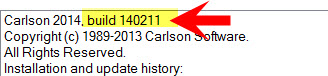
To find your current “build”, open your Carlson desktop software and go to the Help menu and click About Carlson. The current build is listed on the top line in the text window and corresponds to the date it was posted. For instance, the build shown below – 140211 – was released on Feb 11, 2014.


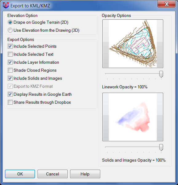
Did You Know… About Carlson’s Export to KMZ (Google Earth) Command?

Carlson Software gives you the ability to export drawing entities directly to the Google Earth application or, alternatively, to a .kml or .kmz file that can be opened in Google Earth. At this time Carlson supports the export of points, polylines, text, solids, images, lines and arcs to Google Earth or .kml/.kmz files.

In Carlson 2014 they have also included the option of sending the Google Earth file directly to a Dropbox account for sharing with clients or other project team members.

The Export to Google Earth command is found in the File menu in all Carlson desktop programs.

Export to KMZ file


Carlson Geoid12 files for SurvCE

For those who have been waiting, patiently or not, for a Carlson update that will allow you to create a Geoid 2012 file for your Carlson SurvCE collector – here is the update from Carlson.


Carlson 2013 Has Been Released

Carlson released the 2013 version of their desktop products today. This includes: Civil Suite, Civil, Survey, Hydrology, GIS, Takeoff, Construction, Point Cloud, Geology, Surface/Underground Mining and Natural Regrade.

The 2013 embedded-AutoCAD versions of Takeoff and Survey have not yet been released.

Unlike previous versions of Carlson that support running on top of IntelliCAD or AutoCAD products 2000-2012, Carlson 2013 can only be run on IntelliCAD or AutoCAD products 2004-2013. This includes AutoCAD, Map, Land Desktop and Civil 3d. Also, anyone using the FREE IntelliCAD that comes with Carlson is eligible for a FREE GIS Starter Kit from Esri which includes ArcMap.

You can download Carlson 2013 here.

If you are using 2012 and are current on your annual maintenance contract, you can click here to look up your new 2013 serial number online. You will need to enter your contact information and your 2012 serial number in order to generate the 2013 serial number. You can find your serial number by opening Carlson Software and going to Help > About Carlson Software > Change Registration.

If you have trouble finding your serial number or would like to know the cost to upgrade to 2013, please email me with your request.

Click here for the full list of improvements to Carlson 2013

Click here for improvements to the General commands in 2013

Click here for the additional data file & conversion support in Carlson 2013

Click here for improvements to Survey commands in 2013

Click here for improvements to Civil commands in 2013

Click here for improvements to Hydrology commands in 2013

Click here for improvements to GIS commands in 2013

Click here for improvements to Takeoff commands in 2013

Click here for improvements to Point Cloud commands in 2013

Click here for improvements to Geology commands in 2013

Click here for improvements to Surface/Underground Mining commands in 2013

Click here for improvements to Natural Regrade commands in 2013


Carlson 2010 Sneak Peek

The 2010 edition of Carlson Software is a few weeks away from general release and is slated to have approximately 400 new features and enhancements. Suffice it to say, there should be something for just about everyone with this release. While by no means exhaustive, here are just a few of the new features that will be found in Carlson 2010 (a few of which were mentioned in the Coming in Carlson 2010 post):

  1. Support for IntelliCAD 6.6 and the AutoCAD 2010 product line – Carlson 2010 will continue to ship with a complimentary copy of IntelliCAD now based on the 6.6 code stream from the IntelliCAD Technology Consortium. Work continues on the migration to the IntelliCAD 7 release which is expected later this year or early in 2010. Carlson 2010 will also support the AutoCAD 2010 family of products including AutoCAD, AutoCAD Map, et. al. Since Land Desktop was officially retired in summer, 2008, now is a great time for organizations to look at Carlson as an alternative to the Land Desktop upgrade path.

    Side note observation… For those Carlson IntelliCAD users out there, don’t forget to inquire about your complimentary Carlson-IntelliCAD GIS Starter Kit from ESRI!

  2. Settings Explorer for CAD Managers – Carlson 2010 introduces an efficient Settings Explorer that allows CAD Managers and users alike to examine, set and migrate settings from machine to machine within an organization.
  3. Layout Manager and Field Text for CAD Drafters – Geared for deliverable output, the Layout Manager and Field Text routines helps automate the creation of plot-ready maps.
  4. Smart Annotation for CAD Drafters and Surveyors – Carlson 2010 helps simplify the annotation typically applied to subdivisions.
  5. Merging of C&G into Carlson Survey for Surveyors – The long-awaited integration of Carlson’s C&G product line with the more traditional Carlson Survey routines provides land surveyors with arguably the most comprehensive collection of survey routines available today.
  6. Drawing Inspector Multi-select for everyone – The highly useful Carlson Drawing Inspector is becoming even more useful with the ability to now display multiple information categories at once.
    Multi-option Drawing Inspector
    Multi-option Drawing Inspector
  7. Template Grade Table for Engineers – In an effort to augment the highly flexible and powerful Template Transition, Template Point Centerline and Template Point Profile routines found in Carlson Civil, a new Template Grade Table provides robust functionality that can be used to design a variety of roadway scenarios. Additionally, the information found in the Template Grade Table can also be utilized in Carlson SurvCE beginning with the 2.5 version of the product.
  8. Edge of Pavement Profiles for Engineers – The ability to produce the graphical results of edge of pavement profiles is now much simpler with Carlson 2010 by giving engineers the ability to extract profile information from the imperical design values that contribute to the vertical aspect of the roadway design.
  9. HydroCAD Linkage for Hydrologists – As originally announced at the 1st annual Carlson User Conference, the data collaboration between Carlson Hydrology and HydroCAD will help users “save time on repetitious data entry, increasing their accuracy, and giving them access to HydroCAD’s extensive rainfall libraries and stormwater chamber specifications.”
  10. Improved Watershed Delineation for Hydrologists – Watersheds in Carlson 2010 can be delineated by three levels: drainage, land use and soil type.

For Carlson Mining clients that might also happen to come across this post, Carlson 2010 offers new functionality for you, too! Check with your Carlson Mining specialist for additional details.

To summarize, Carlson Software is continuing to offer responsive solutions to client-requested technology needs and is standing ready to assist you! Check out our wide-array of technolgy solutions by visiting us on-line at http://www.carlsonsw.com!

Originally posted on Carlson Connection by Ladd Nelson


How Does Carlson Support Their Users? Ask David Farina

I’m going to post a LONG email stream between one of my clients, David Farina, Bruce Carlson and Dave Carlson. You can see the new feature that David requested and Bruce and Dave’s responses. David received a “development” version of the new features approximately a week after submitting this request.

I asked him for a statement describing his experience with Carlson:

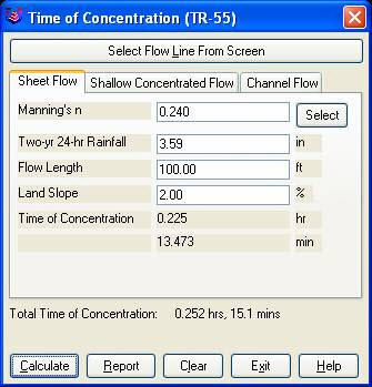
Recently I found that the Time of Concentration input boxes were inadequate under the hydrology portion of Carlson Civil Suite so I emailed a description of the problem to them. I was very impressed to get a phone call the same day. They discussed the problem with me and had a revised program update to me in under a week. I’ve been emailing Autodesk for over a year on problems with Civil 3D and never heard a peep. Needless to say I’m very happy with the customer service I have received from Carlson thus far.

Here is the original question from David Farina on March 4, 2009:

Jennifer,

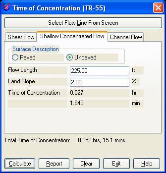
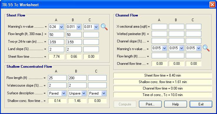
I was going through a mock project to learn the hydrology part of Carlson and noticed a critical deficiency in Time of Concentration input. The review agencies around here want to see the TR-55 method. First, the TR 55 minimum sheet flow needs to be 100’ instead of 300’. They recently changed it per the TR-55 Web site. Second, I don’t think I’ve ever had a project where you didn’t have to split one of these flow types into 2 or more mannings roughness areas.

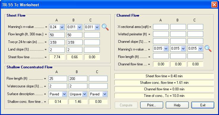
For example:  a flow path that starts on dense grass for 50’ then passes over asphalt for 75’ and back to grass for 200’ would need to be calculated as follows:

 Sheet flow 50’ Grass ->  Sheet flow 50’ Asphalt -> Shallow Concentrated flow 25’ Paved -> Shallow Concentrated flow 200’ UnPaved.

But as you can see the Carlson input only allows for one entry per flow type.

 df_01

 df_02


Below is the Intellisolve version:  Notice the A, B C

 df_031


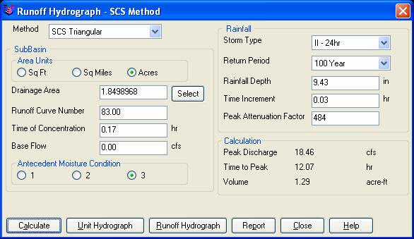
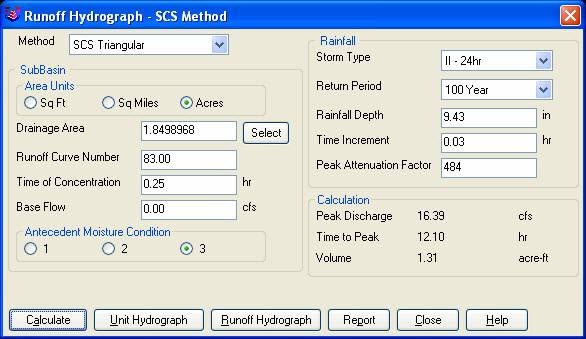
There is a 5.1 minute difference in TC results which results in a 2 CFS difference in the 100yr example below: 

df_04

df_05


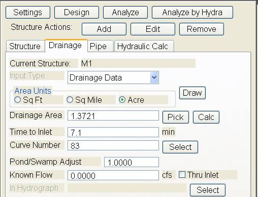
If the above example is that different then I am also concerned about how the Time to inlet is calculated in the example below:

 df_06


df_07

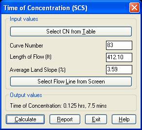
Was the SCS method used to get the 7.1 min value? 

Notice the 7.5 value in the TC dialog to the right. 

This was the value if I SELECT FLOW LINE FROM SCREEN and pick the path that the dialog on the left generates.

Can I generate a report of how the time to inlet was calculated? 

Maybe there can be a button next to the Time to inlet to select TR-55

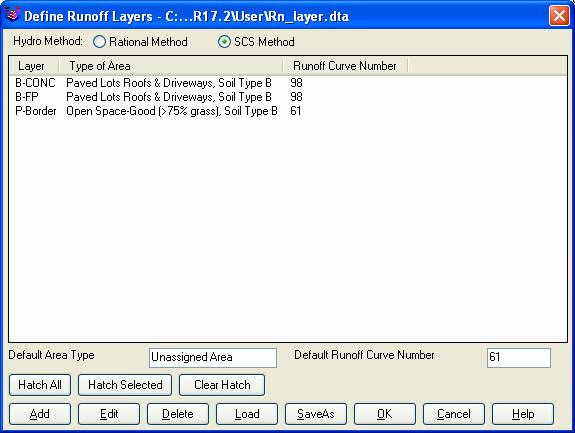
Maybe Mannings coefficients can also be put into the WATERSHED->DEFINE RUNOFF LAYERS to be used for this calc as the flow path passes through each polyline area the same way Carlson already calculates the composite CN.
df_08 

 Will any of this matter if we get HydroCAD and link it to Carlson?  

Just food for thought.


Thank You,

 David Farina

Senior Designer

I forwarded David’s question onto Bruce Carlson, President of Carlson Software, and Dave Carlson, Director of Programming, and received this response from Bruce:

Folks:  Excellent input—this will find its way into the next release for sure.  We’ve spent a lot of time studying Haested and matching numbers there on pipe flows in culverts, for example, covering all conditions—but do need to put to bed Time of Concentration for approved defaults and sub-catchment conditions as they vary within a watershed area.  This Intellisolve example is really helpful.  Also, I took in input at Jennifer’s Statesville, NC presentation Dec. 2007 that mentioned the new 100’ default and also mentioned:

Using Q=CIA, there are new “rules” being published that using larger pipes or it may be larger drainage areas, there is an added multiplier in the form Q=CIA*Q1 where Q1 is a table of values.  I didn’t get the full details, but we need to research this.

And in storm sewer design, if we are compositing the calc of time to inlet using a “short-form” SCS-style method, based on percentage area of various land uses and associated runoff coefficients, we need to have a Report button that documents the results for full vetting and reporting out by users, and we need to incorporate an additional auto-calculated, long-form TR55 time of concentration there as well that uses sheet flow, channel flow and shallow concentrated flow.  One key in all this is to be able to auto-distinguish these flow types from the DTM and land uses and have the forms filled out with default values, which the user can change.  

 Question I’m curious about.  Say you built a gentle 6’wide, 1% slope swale with 6:1 side slopes, hardly noticeable, mowable, between lots in a subdivision.  Would the flow in that be treated as shallow concentrated flow or channel flow?  When would one condition end and another begin, by definition, so we can get real precise on auto-calculating these using layers/land use types and DTM values?

 Good stuff, and it will get done.

Bruce Carlson, PE

Pres., Carlson Software

David added the following:

I think when to use channel flow should be determined by the width of the bottom of the channel and hence how deep the channel gets on an 2yr storm 24 storm.

You could have a channel with 1:1 side slopes but if the bottom was 50’ wide and the flow path started in the channel then

the first 100’ would still be sheet flow in my book. Unless of course a huge amount of water was entering the channel from another basin.

I think the concentrated and channel flow times (being in the fraction of a minute range) are so small and have such a small impact on overall time

compared to sheet flow (fraction of an hour) that you could pick an arbitrary number like 5’ wide bottom and smaller is channel flow and not upset the model.

Sheet flow probably makes up 80 to 90 % of overall TC if it is over grass.

Anyone disagree?

Thank You

Dave Carlson sent this on March 11, 2009


Hi David,

Here’s an update to the Tc by TR-55 routine that allows unlimited number of breakouts. This update is for Carlson 2009 on Acad 2007-09. To install, unzip and copy the arx to the Carlson2009LSP folder. Let me know if you need a different version or have more suggestions.

For the Storm Sewer Network routine, I put it on the to-do list to add a Select button next to the Tc to show the components that make up the Tc like the Select button does for CN. Also we will looks at adding Manning’s n to the Define Runoff Layers for use with Tc calcs.

Thanks for the input.

Dave

Originally posted on Carlson Connection by Jennifer Dibona


Coming in Carlson 2010

I’m not privy to the “official” list of coming updates, but I can share a few things that I know will be in the next release. Most of these come from “wishlist” items I have submitted on behalf of my clients.

The folks at Carlson are welcome to add their 2-cents in the Comments of this post or on Direct From Carlson.

Option for placing building footprint a distance off the building setback line.

Currently, the LotNet command places the building footprint exactly on the midpoint of the building setback line. We heard the request several times to have the option of placing the footprint some distance behind the setback line. It will be in the 2010 release.

C & G Survey

Instead of having two separate survey programs, Carlson will be incorporating C & G as a separate set of menus in Carlson Survey in 2010.

Basic IntelliCAD Menu

If you’re running Carlson on top of an AutoCAD-based program, you have an icon or menu option to switch over to an AutoCAD menu that has basic Draw commands such as line, pline and text and basic Modify commands such as copy, explode and pedit. Although it’s not easy to get to right now, IntelliCAD has a similar set of menus and toolbars. Carlson 2010  stand-alone with IntelliCAD will have a menu item and toolbar icon allowing you to easily switch over to the IntelliCAD menus and then back again to the Carlson menus.

Lookup table of curb slopes for super-elevation transitioning

This new feature will handle curb transitions like those shown in this NC DOT detail drawing.

Originally posted on Carlson Connection by Jennifer Dibona


IntelliCAD Update for Carlson Products – 2/2/2009

 The most recent IntelliCAD Update for Carlson can be found here:

http://update.carlsonsw.com/entov/c2009_icad_post65_install.exe

From Carlson:

It contains the fixes based on user input and crash submissions since we released 6.5.

In particular, the following features and crashes has been addressed or at least a fix has been attempted:


1) Crash on mouse move
2) Crash on save (during exit?)
3) Another update to image engine to correct problems in the last update
4) Crash during printing or redraw after real time zoom
5) Numerous “small” crashes
6) Crashes during drawing opening or saving
7) Right click menu is added for entity modifications ( this requires menu reload and will reset the menus and toolbars). To reload the menu, type MENU and select icadbase.mnu file.
8) Slow autosave/save has been addressed or at least improved.
9) Font mapping problems have been addressed

In case if this patch makes matters worse for you, the older patch is available here: http://update.carlsonsw.com/entov/c2009_icad_6_6_17_41_install.exe . Simply run it to restore to the last version.

Originally posted on Carlson Connection by Jennifer Dibona


Top Myths About Carlson Software

I’m asked many of these questions on a fairly regular basis and thought it was time to look into some of them and provide the fullest answer I could. Where possible, I’ve researched and found the answer myself. In a few cases I had to rely on Carlson representatives to supply the answers.
  
Myth #1  Autodesk stopped working with Carlson in February 2008. 
  
 False. In February 2008 Carlson simply stopped being a reseller of Autodesk products.

In other words, if you want to run Carlson on top of AutoCAD, Map, Land Desktop or Civil 3D, you’ll have to buy it from an Autodesk reseller instead of from Carlson. Carlson remains part of Autodesk’s Developer Network (ADN) and is listed on Autodesk’s partner page. The ADN designation provides tools to developers to help build their products on top of Autodesk products. As a point of comparison, Eagle Point Software is also a development partner of Autodesk.
  
 
Myth #2  Carlson is owned by Autodesk or, (“bonus”-myth) Carlson will be sold to another, larger software company. 
  
 False. Carlson Software was started in 1983 by Bruce Carlson and remains a private, family-owned business. No one can absolutely guarantee the future, but I have heard Bruce Carlson speak many times about the value he places on competition in the marketplace and his belief that the consolidation of many other software companies has come at the expense of the end-user of the software.

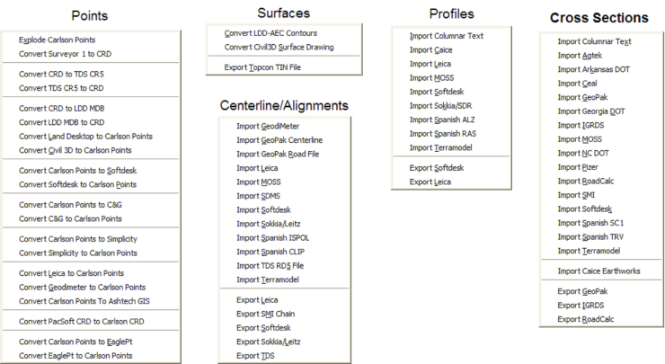
Selling out? I don’t see it. But partnering? Yes. Carlson places a great deal of value on working with any company who wants to work with them.   Click on the image below to see the many different programs Carlson imports data from and exports data to.

Carlson Import and Export Options

Myth #3  Because Carlson Software uses basic AutoCAD entities instead of “intelligent objects”, it does not have 3D or dynamic abilities. 
  
 False. Carlson Software uses basic AutoCAD entities so that all drawings produced by their programs can be easily shared with any other DWG- or DXF-compatible program, regardless of version. Carlson has figured out a way to have the dynamic reactions work on basic entities such as lines, polylines and text. One example would be having profiles and storm drain structures automatically adjust their elevation as a centerline alignment is edited and changed along a surface. And, all of this happens without having to fight the dreaded “proxy objects”!  
 
Myth #4  Because Carlson now works on top of Intellicad, it no longer works on top of AutoCAD-based products. 
  
 False. Carlson Software has always worked on top of AutoCAD-based products and, if you listen to Bruce Carlson discuss the issue, hopes to always continue doing so.

In April 2008, Carlson began giving their customers an IntelliCAD-based “stand-alone” copy of their software with every purchase of Carlson Civil, Survey, Hydrology, GIS, TakeOff and other programs. (IntelliCAD is widely described as an “AutoCAD-clone”. You can read more HERE.). This, again, gives more power and options to Carlson users because it allows the user to choose whether to run Carlson on top of practically any version of AutoCAD, AutoCAD Map, Land Desktop, Civil 3D or on top of IntelliCAD.

Also, with their Sight Survey program (launched in 2008), Carlson created their first program to run on top of MicroStation.

At last year’s 25th Anniversary users’ conference, Bruce Carlson stated that Carlson hopes to have their software working on 4 different platforms within the next few years: IntelliCAD, AutoCAD, Microstation and ESRI. 
  
 
Myth #5  Carlson doesn’t have CIVIL “BIM”-ability. 
  
 First, the premise of the statement is incorrect. BIM (Building Information Modeling), by definition, has no relationship to the civil engineering industry. It is architectural in scope and refers to actual buildings and facilities.

However, for several reasons there has been a push to re-define the term BIM to apply to Civil Engineering (in general) and Civil 3D (in particular). When discussing BIM in the context of Civil Engineering, it simply means that a software program has the ability to:

  • design to specific criteria
  • show a great visual representation of all the components of your project in 3D view and
  • dynamically reflect changes to your project.

Can Carlson Software do all that? Absolutely.

Carlson can, and has been able to, produce true 3D models of civil/survey/utility project sites for years. These models can be viewed in 3D and quantities are dynamically updated whenever the model changes.

Because Carlson has strongly served the U.S. mining industry for over 20 years, they long ago developed features for grading, material quantity calculations and surface viewing and visualization to meet the demands of this industry. In fact, the civil industry pales in comparison to the mining industry in regard to these demands.  
 
Myth #6  Carlson has only been developing civil software since 2007. 
  
 False. To make sure I got this right, I asked the folks at Carlson for help and received the following in response:

Bruce Carlson began developing his software for the mining industry in 1983. By 1984, the program was able to extract profiles and cross-sections, calculate volumes and design road profiles. 3D Surface viewing abilities have been available in Carlson Software since the early 1990’s.

Carlson developed the stand-alone Carlson Survey program in 1996 and in 1999 Autodesk contracted to market and sell a version of it called “Autodesk Field Survey”. Autodesk did away with Field Survey after a few years and Carlson migrated most users over to Carlson Survey where it has grown to become a favorite of surveyors.

Various civil features were organized as modules in a package called SurvCADD that was released in 1989. The civil engineering routines were renamed as Carlson Civil in 2006.

The first Hydrology module for Carlson was released in 1993. It was re-packaged as Carlson Hydrology in 2006.

Carlson Hydrology was the first and, I believe, is still the only H & H software to function entirely within the DWG-environment. If I learn differently after this document is made public, I will post a correction in this space.
  
 
Myth #7  Carlson may have found a spot in some surveying firms, but larger firms aren’t using it. 
  
 False.  Again, I requested generic customer data from Carlson and was told that,

Among our 30,000+ users, there are many DOT agencies and also ENR Top 50 firms using Carlson Software. Carlson Software is very experienced in working with large firms, due to their mining background. All 20 of the top 20 U.S. coal companies use Carlson Software at some level, most being standardized on the software for mine planning and design.

As far as my personal experience, I’ve only been working with Carlson Software for a couple of years and companies I work with tend to have fewer than 25 users. I can personally say that I have seen or know of a few large firms who have moved to or are in the process of moving to Carlson.

These do not include the many customers of mine who have recently let their software contracts lapse, purchased one or more seats of Carlson and have told me they plan to purchase and implement Carlson when the economy rebounds. 
  
 
Myth #8  Carlson Software does not support the full project lifecycle – Concept to Completion. 
  
 False. I think Carlson probably has the project lifecycle covered better than any other software firm in existence.

Carlson Software has data collection, survey processing, civil design, hydrology, GIS, construction material takeoff and machine control software in their stable. 
  
 
Myth #9  Carlson Software doesn’t have the support system in place to adequately support its users. 
  
 False. Carlson provides free technical support directly out of their Maysville, KY and Boston, MA offices. Again, I have heard Bruce Carlson say that keeping tech support free and in-house ensures that their software will remain easy-to-use and that the company will always be responsive to the wishes of their customers.

If a bug or other problem with the software is encountered and logged into Carlson’s tech support department, the corrected files will be emailed to you as soon as the programmers develop the fix. Periodically a collection of the updated files will be released to all users as a maintenance patch. These updates are available to all users whether or not they are under a maintenance contract with Carlson.

I received this testimonial from a customer on March 13, 2009.

“Recently I found that the Time of Concentration input boxes were inadequate under the hydrology portion of Carlson Civil Suite so I emailed a description of the problem to them. I was very impressed to get a phone call the same day. They discussed the problem with me and had a revised program update to me in under a week. I’ve been emailing Autodesk for over a year on problems with Civil 3D and never heard a peep. Needless to say I’m very happy with the customer service I have received from Carlson thus far.”

David Farina, CCAD Engineering
– Greenville, SC

Other examples of Carlson’s responsiveness:

Example 1: The ability of the Carlson Civil & Hydrology “Design Bench Pond” command to have multiple interior benches was added to the software after an attendee at a workshop I held in Raleigh, NC in December 2007 requested it.

Example 2: In the LotNet command, the prompts asking users to specify minimum and maximum building offset distances for lot layout generated too many tech support calls. In the next release, the prompts were re-worded to make the intent more clear.

Example 3: The LotNet command now allows you to designate “sub-areas” (such as wetlands, stream buffers, poor soils, etc.) to be excluded from your area to be subdivided during the lot layout routine. This request came from a prospect during a demonstration in Raleigh.

Example 4: I understand that Carlson’s tech support team was bombarded by requests to change the default cul-de-sac location from the “Start” of the road to the “End” of the road in the RoadNet command. This was changed in the 2009 release.

Example 5: The ability to draw multiple building pads inside lots during the lot layout routine in LotNet was requested by a firm out of Savannah, GA. 
  
 
Myth #10  Carlson Software can’t share data with Land Desktop or Civil 3D. 
  
 False. Carlson has many tools in their software to import civil/survey data from and export data to Land Desktop and Civil 3D. It can be said that Carlson Software works with Civil 3D data as well as Land Desktop or any other civil/survey software and also works with Land Desktop data as well as Civil 3D or any other software.

Carlson has LandXML import and export functionality, can directly convert Land Desktop points and contours into Carlson points and contours and also imports a Civil 3D surface as elevated contours.

Regardless of the civil/survey software being used, LandXML is the best mechanism to import/export a surface model because it maintains the TIN lines of the surface. 
  
 
Myth #11  To be continued. 
  
 If anyone thinks of other question(s) they’d like to supply, please email me HERE. I’m open to suggestions and don’t mind expanding beyond 10 Myths.

Originally posted on Carlson Connection by Jennifer Dibona

1 of 1