This article originally appeared in the December 2011 issue of Professional Surveyor magazine.
After we published “Understanding Field to Finish” in the September issue, I received more feedback and questions than I had for any other article to date. Although my plan for this month’s column had been “CAD Standards Part 2” (Part 1 is in the June issue), it makes more sense to answer some of the questions that were sent my way about Field to Finish first.
(I am using Carlson Survey for the examples in this article, but corresponding features and commands should be available as part of the Field to Finish feature of most other programs.)
The majority of readers’ questions revolve around how to code field descriptions and generate linework for multiple point codes. You use multiple point codes when you have a single field shot that defines more than one feature—for instance, a shot that locates both an edge of pavement and a sidewalk. However, before diving too quickly into multiple point codes, let’s make sure we have a good understanding of the different ways that you can use descriptions and linework codes to generate linework.
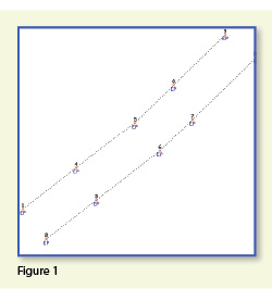 In Figure 1, the dotted lines represent the actual edges of pavement that exist in the field. Points 1-10 have a description “EP” designating them as Edge of Pavement.
When locating features that are generally symmetrical and that have two “sides,” such as a road, a sidewalk, or even a ditch having two tops of bank, we have a choice in how best to collect the points. Depending on field (and traffic) conditions, it may make more sense to take all the shots along one side of the road before crossing the road and taking all the shots along the opposite side.
The other way to collect shots is in what we call Zorro fashion: where we crisscross the street, taking shots on both sides, as we progress down the road. You can see that we used the Zorro style when taking shots in Figure 1. Point 1 is on the northwest side of the road, and shots 2 and 3 are on the southeast side. We then crossed back over to the northwest side to pick up 4 and 5, and so on.
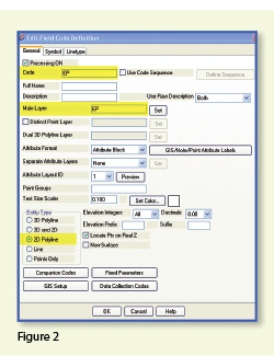
 To draw the linework for the edges of pavement, you must create a field code for the EP description. You can see from Figure 2 that it requires only a couple of specific settings to indicate that this is a 2D polyline type of entity and on what layer the polyline is to be created.
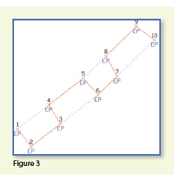
With the EP field code defined, using Field to Finish to draw points 1-10 generates the linework on layer “EP” (shown in red in Figure 3). Obviously this is not quite what we expected. I like to say that this is an example of the software doing exactly what we told it to do … rather than what we meant to tell it to do. So, we need to make a couple of adjustments.
The software understands only that it’s expected to connect all of the EP points with a 2D polyline. Carlson Survey allows you to choose whether the field code points are connected in “Sequential” order or “By Nearest Found.” The default setting is “Sequential,” which is why it connected the points the way it did. Unless we provide a little more information, there is no way for it to differentiate one edge of our pavement from another. If we make a minor change in the descriptions we use, we can have the program generate the linework correctly.
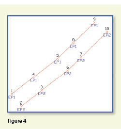
 Rather than calling all edge of pavement points EP, we can use a number to modify the description so that we can tell the two polylines apart. We can use “EP1” for the northwest side and “EP2” for the southeast side. Now, when we redraw the points using Field to Finish, we end up with Figure 4, which is exactly what we wanted.
It is important to note that the field code does not change even though we’re now using EP1 and EP2 instead of EP. The field code is still “EP.”
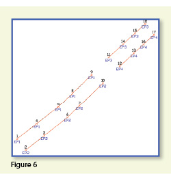
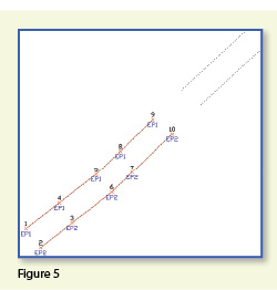
Let’s introduce just a little more complexity. Beyond points 1-10, we have an extension of this road with two additional edges of pavement that are shown as dotted lines in Figure 5. We do not want to continue the linework from points 9 and 10 but to start new polylines instead.
If we use descriptions EP1 and EP2 for the new edges of pavement, Field to Finish will assume we are continuing the other edges of pavement. So we must, again, have a way to differentiate the new edges of pavement from the ones drawn previously.
 Using the same method as in the prior example, we can use descriptions “EP3” and “EP4” for the new edges of pavement. As you can see in Figure 6, this leaves us with the four separate polylines that we wanted.
The only drawback here is that the numbering of each distinct edge of pavement could get confusing on a large site. In this example, once they’ve been used, EP1 or EP2 can’t be used again without Field to Finish thinking all the EP1 points are part of the same polyline.
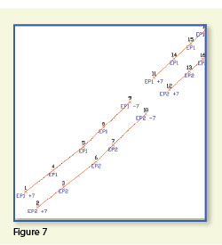
The good news is that it only requires another small coding difference to allow you to re-use EP1 or EP2 again. In Figure 7, we still use the EP1 and EP2 descriptions, but we use them in combination with special linework codes “+7” and “-7.” In Carlson lingo, “+7” is the default code to “Start a new polyline” and “-7” is the code to “End the polyline.” You can see that once we have descriptions “EP1 -7” and “EP2 -7” at points 9 and 10, we start new polylines by reusing EP1 and EP2 at points 11 and 12. As long as you’re diligent about using the “-7” special linework code to end the previously drawn polyline, you can reuse the descriptions.
Multiple Point Codes
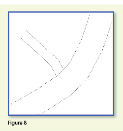
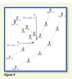 You use multiple point codes when you have two site features (such as the edge of pavement and a sidewalk) that intersect. As you can see in Figure 8 there are two points where a sidewalk meets the edge of pavement. In Figure 9, you can see the descriptions we used so we could have Field to Finish process points 5 and 6 as part of both the EP and SW linework entities.
Point 5’s description “EP1 SW1 +7” means that this shot is a vertex along the current EP1 polyline and also starts a new polyline named SW1 to define the edge of the sidewalk. Point 6’s description “EP1 SW2 +7” means that this shot is also a vertex along the current EP1 polyline and starts another new polyline named SW2 for the other side of the sidewalk.
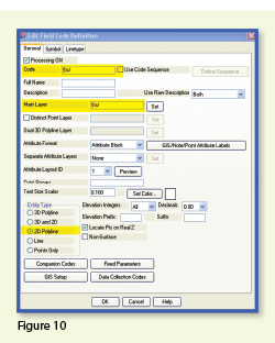
To have Carlson’s Field to Finish process these points as shown, we had to create only one additional field code: the “SW” code for sidewalk. We set the Entity Type to 2D Polyline and set the Main Layer to “SW” (Figure 10).
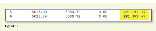 Now, let’s take a closer look at the descriptions for points 5 and 6 (Figure 11). In Carlson Survey, if you use a space between two descriptions, the program allows you to process them separately using the two corresponding field codes. The corresponding field codes used to process these descriptions are EP and SW so Carlson will process the same point twice, first using the EP field code and then again using the SW field code.
 Because having a space in a point description is an indicator to Carlson that multiple field codes may need to be processed, it is a best practice to avoid using spaces in your descriptions. Using a description such as 24” RCP PIPE can create several problems, but the main one is that Carlson will think it is supposed to process three separate field codes: one for 24”, one for RCP and one for PIPE. A better description would be PIPE/24” RCP. In this example, a field code named PIPE would be processed. And, because a forward-slash (/) separates PIPE from 24” RCP, Carlson considers everything after the slash as a comment and will ignore it when processing Field to Finish.
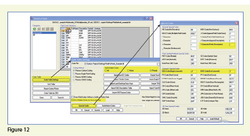
If you follow the maze of dialog boxes in Figure 12, there are several settings to take note of:
- In the Code Table Settings dialog box, there are three possible settings for Split Multiple Codes.
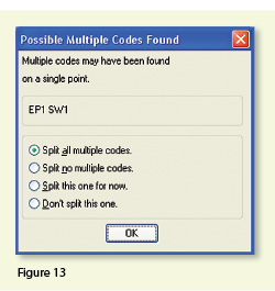 If you select “All,” any point description that contains a space will be processed as a multiple point code. If you select “None,” all spaces will be ignored when it comes to processing multiple point codes. If you select “Prompt,” you will be prompted with the dialog box from Figure 13 each time a space is encountered in a point description.
- In the Code Table Settings dialog box, select the option to “Use Multiple Codes for Linework Only.” This causes Carlson Survey to create both the EP and SW linework on their respective layers but only one point (created on the layer specified by the first field code). If you do not select this option, the program will create two points with the same point number but with different descriptions. Each point will be inserted on the layer specified by its respective field code.
In the Special Codes dialog box, you can see the default settings and are able to customize the Special Codes used to process descriptions, points, and linework in Field to Finish.
With that, I hope I’ve been able to answer a few more of your Field to Finish questions. Please don’t hesitate to call or email as needed. I hope everyone has a fantastic holiday season, and I’ll see you back here in 2012!
This article originally appeared in the December 2011 issue of Professional Surveyor magazine.