BIM is not GIS

As someone quite entrenched in both disciplines (Civil and Architectural), I’ll add my 2 cents worth on the BIM vs. GIS subject.

In my opinion, BIM and GIS are both “methodologies” rather than “products”. The acronyms each have their own meaning and refer to designing, building, and managing information in a full life-cycle.

Each discipline has its own standards; from CAD standards to design standards (think of AIA vs. AASHTO), but both BIM and GIS rely on correct As-Built data to provide accurate information about their models.

BIM
The National BIM standard states the definition of BIM as:

BIM is best thought of as a digital representation of physical and functional characteristics of a facility…and a shared knowledge resource for information about a facility forming a reliable basis for decisions during its life-cycle; defined as existing from earliest conception to demolition.”

Autodesk has taken the BIM acronym that has provided a great deal of success with their Architectural Modelling packages and applied it to their Civil products as well. Their logic appears to be that its a “3D” product, therefore it is a “BIM” product. I believe that it is irresponsible to change terminology to simply advance product sales.

On the Autodesk Web Site, Autodesk lists a number of products as being “BIM” products:

  • Revit
  • Navisworks
  • Design Review
  • AutoCAD LT
  • + several more

With the acronym meaning Building Information Modelling (with building being a verb OR a noun), its interesting to see products such as AutoCAD LT and Design Review being shown on the list.

Revit
Revit is a Design Tool that allows the storage of certain pieces of information as well as the ability to add custom fields (heating capacity, cooling capacity, etc.) to the actual objects.

Navisworks
Navisworks integrates information from multiple data sources to provide a cohesive collection of information (graphics and data) to analyze things such as clash detection (HVAC duct work clashing with structural components, etc.).

AutoCAD LT
AutoCAD LT is Autodesk’s low-end design package. Apparently, any DWG file creation tool is now a BIM product as well.

Design Review
Design Review is a light-weight DWF viewer and markup tool. While it has been used as a backbone of products such as FMDesktop, its neither a Design tool, nor a Modelling tool.

FMDesktop
Absent from the list is FMDesktop. FMDesktop was one of Autodesk’s tools for managing the Building Information and Autodesk just dropped the product (Note: There are dozens of Facilities Managent Products available that provide similar capabilities such as FM:Systems, Archibus, Tririga, Manhattan, Cadapult, Famis, and more).

In the 2006 – 2007 time frame (when Autodesk acquired FMDesktop), Autodesk themselves showed customers Power Point slides regarding BIM. These slides showed where the “Design”, “Build”, and then “Operate and Manage” processes were performed. FMDesktop was Autodesk’s solution to tell the story of the building lifecycle and where the information was to be managed. These were broken down into 2 sections: The “Data Collection” piece and the FMDesktop piece.

Data Collection incorporated the Design (several disciplines such as Architects, MEP Systems Engineers, and Structural Engineers) as well as the majority of the Build process. The FMDesktop piece overlapped the Build process and then took over for the “Operate and Manage” process.

In my opinion, building that model of information AND managing that information is the true test of a “BIM” solution. There is no 1 product that is a “BIM” product. Its a series of technologies that are incorporated to provide the “information”.

Ultimately, a database component is required to work with the graphical representation of data (which certainly could be referred to as the “Building Model”).

GIS
GIS is BIM’s counterpart whereby Geographic (position on the planet) information is being stored and managed.

Most end users might think of GIS solutions as Google Maps or Google Earth where they can enter an address and out pops a graphic representation of that location or directions on how to get there. The graphic is just the tip of the iceberg. Without the data, the graphic would simply be a pretty picture.

Just as with BIM data, GIS data utilizes design tools to build the graphics and As-Built data and then tools to expand upon the As-Built information.

While there are a number of individual products on the market to assist in the creation, manipulation and distribution of GIS data, a complete GIS system involves more than 1 product or techonology.

A couple of the common Design Products are: Autodesk Civil 3D and Carlson Civil Suite

AutoCAD Civil 3D
Civil 3D is an object-oriented design tool for Civil Engineering applications. Because the tool is object oriented, the end product is not easily distributable. The data can be transferred to other links in the GIS solution chain by using technologies such as LandXML, but the graphical interaction is lost in this process (i.e. the objects are lost).

Carlson Civil Suite
Carlson’s Civil products work with DWG files in an AutoCAD or IntelliCAD DWG format. Because the data is stored as compatible DWG information with external data files, the data is easily transferred to other products in the GIS solution chain.

Managing the data developed in the design process is the next component of the GIS life-cycle. A number of products provide those solutions: ESRI ArcGIS, Vueworks, and Custom Mapguide Solutions.

ESRI ArcGIS
ESRI’s shp (shape) and adn (coverage) files are quite possibly the most prevalent GIS specific data files available and are often integrated in GIS solutions. ArcGIS allows GIS solutions to be deployed similar to FM solutions in the BIM world.

Vueworks
Vueworks is an organization that builds GIS and Work Management solutions using the ESRI base applications.

MapGuide
MapGuide is Autodesk’s development environment to build GIS applications. It is often used in concert with ESRI, Microstation and Autodesk data files.

GIS Standard
While there is not yet a concensus on a singular GIS standard, there are independent Spatial Data Standards employed by each digester of GIS data. You can view some of those here:

Both GIS and BIM perform very specific functions in accordance with their own disciplines. While the terminology is often mis-used, they refer to unique information systems; BIM in the structural facility world and GIS in the geographic world.

Originally posted on Carlson Connection by Jon Luby


BIM for Civil… Not

Several months have passed since I made my original post BIM This, BIM That… What is BIM?. In that time, I have asked a lot more questions, read a lot more on the internet and had a lot of discussions with Ladd and Felicia and also read the post by one of our commenters. I think I’ve developed a more concrete idea about BIM and how it applies, or doesn’t, to the civil/survey world and where the various software packages stand in regard to their “BIM-ability”.

Now, after all this additional information has percolated in my brain, I’m drawing two main conclusions:

1. It’s a fact that the term BIM as it’s always been used applies to actual BUILDINGS – the noun form of the word. But, more specifically, it  starts with construction drawings/design data but then incorporates the as-built data and, over time, continues to grow and collect data through the entire lifespan of the building.

Nothing in all this discussion of “BIM for Civil” gets beyond construction drawings and design data of a civil project. Autodesk is trying to stretch the definition of BIM to cover Civil 3D even though they never move beyond the design process with it either.

Remember, we do not talk about “BM” or Building Modeling. And, we don’t work with “GS” or Geographic Systems. The “I” is THE critical factor. And the “I”, or Information, piece of BIM is so valuable because it chronicles and helps manage the building through its lifespan.

To be able to legitimately call what we’re doing with our Civil programs “BIM”, we would need to have a mechanism to attach some sort of database or information to the objects in our drawings.

I know, I know… that’s why Civil 3D is so great – you can attach data to the objects. But, remember, we’re talking about attaching AS-BUILT data to these objects. Even though we could attach data using Carlson GIS or AutoCAD Map or ESRI, it’s simply not part of our current project scope to go back into our construction drawings and update them with as-built data so that:

  • maintenance schedules are attached to roadway template surfaces based on asphalt type,
  • model numbers are associated to pump stations or
  • inspection reports and flow rates are attached to fire hydrant blocks.

My conclusion here is that neither of these products – Carlson nor Civil 3D – meet the true definition of a BIM for civil. Until we start addressing the Information piece for the lifetime of a project, starting with the as-built data, using the term BIM is wrong.

In my opinion, if anyone has the lead on this in the civil arena, it’s ESRI.

2. Just because we don’t yet attach as-built data to our objects doesn’t mean that the data we do attach to our objects isn’t valuable. But, leading to my 2nd conclusion, why is it valuable? It’s only valuable if it can be shared. And this is where I believe Carlson has the undisputed edge. The image below shows the number of formats and other programs that Carlson is able to import data from and export data to.

carlson_importexport

Originally posted on Carlson Connection by Jennifer Dibona


Dewberry – Aligning Technology with Business Strategy

Some of you may have heard David Palumbo, PE, Technology Manager for Dewberry, at the Carlson User’s Conference back in April.  For those that missed his presentation, his story has been published in CE News this month.  Read about the process Dewberry used to evaluate new technology, its impact on their business methodology, and how they planned the roll-out and implementation.  Regardless of the size of your company or the software you use, there are some good tips and pointers in this article.

http://www.cenews.com/article.asp?id=3928

Originally posted on Carlson Connection by Felicia Provencal


Carlson Webinars – BIM, GIS and CAD Standards

Carlson Software recently asked Felicia and me to present webinars on topics we have particular interest in or specialize in. 

Felicia’s webinar on BIM, GIS and Carlson Software can be viewed here: BIM, GIS and Carlson Software Webinar

My webinar on CAD Standards can be viewed here: CAD Standards for Carlson Software with AutoCAD or IntelliCAD

Originally posted on Carlson Connection by Jennifer Dibona


BIM, GIS and Carlson Software Webinar

Felicia Provencal’s webinar for Carlson Software on the topic, “BIM, GIS and Carlson Software” can be viewed or downloaded here.


What’s In Your Surface?

With the adoption of machine control for construction, the ability of various GIS systems to accept 3D data, and now with the expansion of the term BIM to cover elements outside of a building proper, surface modeling has become a critical aspect of any project.  Since so many elements down the line rely on the surface model, it is critical that the model be as accurate as possible and free of errors.  This article will be the first in a series that will take a look at various tools and options within the Carlson product line to ensure the accuracy of your surface models, sometimes known as triangulated irregular networks (TIN) or digital terrain models (DTM).

In this first article, we will take a look at quality assurance/quality control (QA/QC) and how it applies to surface modeling.  This is an essential step of the model building process, and one that is often overlooked by software manufacturers.  For most people, the QA/QC process generally involves examining the contours and looking for issues, or spot-checking points on the surface.  All current surface modeling software allows for the generation of contours and spot-checking, but these rely on the user to manually review the entire surface after it has been built.

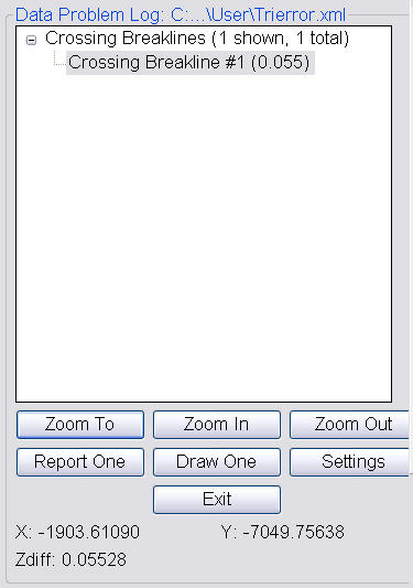
Carlson Software is one of the few products that include an error checker as part of the surface building process.  Most other programs either return a generic error message, or simply fail to complete. If you use the Triangulate & Contour routine, an error log is displayed showing any major issues after the surface data is processed.

Surface Error Log

The issues listed include the following:

  • Crossing breaklines
  • T-Intersections between breaklines
  • Vertical faces

If there are no issues with a surface model, the error log is not displayed.  You can use the various options to change the sensitivity of the error checker, and to highlight any issues found.  Simply select a single error on the log, then click Zoom In.  You can then either correct the errors using any of the surface editing tools, edit the original data (such as the breaklines) and rebuild, or choose to ignore the errors if they are minor.

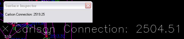
Although no errors may be found as part of the surface creation, there may still be errors in the surface model resulting from bad data.  Once the surface has been built and any build errors have been corrected, you should do a manual review of the spot elevations and contours.  The easiest way to check and verify spot elevations in Carlson is by using the Surface Inspector, which is available from the Surface pull-down menu of various modules.  After you select the Surface Inspector command, you can change options as to which surface(s) you want to examine, as well as labeling settings.  Once this has been done, move your cursor over the surface previously specified and a floating dialog box will show you information about that surface.  Click anywhere on the surface to label a specific point.

Surface Inspector

Press Enter to exist the Surface Inspector.

By taking just a little time to verify that your surface model is accurate and free of errors, you can save time, money, and effort in the later stages of your projects.  The Surface Error Log is an invaluable tool for locating any errors and flagging them for editing at a later time.  The next article in this series will look at checking a surface model using contours.

Originally posted on Carlson Connection by Felicia Provencal


Online Training – Friend or Foe?

With the economy what it is and everyone trying to get as much bang for their buck as possible, I’m finding that online training for your CAD software programs is an increasingly popular and cost effective option.

Although this post describes my personal approach and may be different considering your trainer, hopefully it will answer some of your questions about online training and will encourage you to give it a try.

How does it work?
There are several online services that trainers may use for online training. WebEx, GoToMeeting and GoToWebinar are all very commonly used and popular. My preference is GoToMeeting and GoToWebinar as they have a very low footprint on your computer and are simple to use. When first entering an online meeting, a small installation of the program occurs allowing you to view and interact with the presenter’s computer.

GoToMeeting is smaller scale and better for personalized training. GoToWebinar can handle up to 1,000 “attendees” and is typically used for presentation or demonstration to a large group.

Some of the online meeting services are free, but most require a monthly fee. The fee is paid by the organizer who then has the ability to schedule meetings/webinars in advance or “Meet Now” for meetings on the fly. Your organizer will either email you a link to the meeting site or can tell you the link on the phone. Each meeting has a unique “Meeting ID” that you’ll enter at the main page.

GoToMeeting is typically used for standard training where more than one person may need to show their screen and/or be given control of the mouse and keyboard. This interaction can take place in a variety of ways. When in a meeting, anyone can be given (and must accept) the “Presenter” role which allows others to view their computer. And, even though the Presenter always has priority, control of the mouse movement and keyboard entry may be granted to others in the meeting. This allows someone else to work on my computer remotely.

The audio portion of the training usually takes place by calling in on a conference call line supplied by GoToMeeting. VOIP (Voice Over Internet Protocol) is also available allowing you to use your computer’s speakers and microphone but it is not recommended because of quality.

GoToWebinar is used for larger scale demonstration and presentations and can accommodate up to 1,000 Attendees. Online Webinars are generally structured to have one or more Presenters making the presentation.

Like GoToMeeting, the audio portion of GoToWebinar usually takes place by calling in on a conference call line supplied by GoToWebinar. However, in a Webinar setting, the Attendees are muted automatically by the Presenter so that everyone isn’t blessed with the sound of crinkling potato chip bags and elevator music when someone puts the phone on hold. The Presenter has the ability to un-mute one or more Attendees as needed. The audio of all Attendees is managed by the Presenter by having each Attendee enter a unique “Audio PIN” upon arrival.

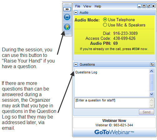
GoToWebinar has 2 ways to ask and respond to questions from Attendees. The Control Panel has a “Raise Your Hand” button that notifies the Presenter there is a question. Depending on time constraints, the Presenter may decide to un-mute and answer the question during the online session.  If there are more questions than can be answered during a session, the Organizer may ask that you type in questions in the “Questions Log” so that they may be addressed at a later time.

GoToWebinar_ControlPanel2

Pros and Cons 
I’ve put together what I consider to be the Pros and Cons of online training for CAD Software programs. Please pitch in and offer your comments.

Pros

  • Can eliminate travel time and expenses
  • Very cost effective option for customized one-on-one training
  • Allows for personalized, absolutely customized training because it’s normally one on one.
  • Can’t find a local trainer? No problem. Felicia Provencal can train you from Hawai’i – although you may want to go to her!
  • Can be set up within minutes if there is a pressing technical support issue or project that suddenly comes up.
  • Can be scheduled in shorter blocks of time – one of the best ways to make sure you retain what you are taught. I like to schedule 2 hours maximum per session.
  • Shorter blocks of time allow for easy customization of training topics from one session to the next. If more time is needed on certain features, it’s easy to squeeze in another 2 hour session.
  • It IS interactive!
  • All sessions can be recorded and played back at your convenience for a refresher.

Cons

  • Some people are more comfortable sitting beside and working directly with the trainer
  • It’s less interactive than hands-on, in person training.
  • For hands on training and depending on the material being covered, it may not work as well if you have several folks needing training at one time.
  • Requires a high-speed connection and a telephone headset allowing two hands on keyboard. A speakerphone can be used as long as feedback doesn’t become an issue.

Real World Example
I recently worked with a client from out of state. He is a grading contractor who thought he needed Carlson TakeOff training but, after some discussion, realized training in basic CAD (IntelliCAD) needed to come first and then TakeOff training.

The initial proposal was for me to travel there and spend 3-4 days training this client plus a second person (a competitor, in this case) who needed the same training. Both of them decided to give online training a try.

We scheduled online training for every morning one week. I worked with one from 7:30 – 9:30 am and then with the other from 10:30 – 12:30 pm. After the 3rd day, we had covered so much material that one asked to skip the next day so he could work with it himself and apply what he’d learned so far.

We ended up skipping two days. By the time we met again, he’d worked with it enough and become so much more proficient with the basic CAD operation that we were able to fast-forward through the next couple sessions and started working on his current project. Another subsequent session was cancelled because the rain finally stopped!

And then a few days later, he needed to get his project finished and out to bid. So, after our first session one morning, we set up another session at 4:00 that afternoon and worked until almost 7:00 that evening.

Both customers ended up very happy with the amount of material we covered and where they were with the software when we wrapped up our regular training. They still have the video recordings of the training for their reference to go back to when needed. In the end, the cost was almost the exact same as it would have been had I fulfilled the original proposal but they both learned and retained much more because the training was customized and personalized to their specific jobs.

Originally posted on Carlson Connection by Jennifer Dibona


Carlson-IntelliCAD GIS Starter Kit from ESRI

Those currently using Carlson with IntelliCAD are eligible for a new “GIS Starter Kit” from ESRI. The Kit includes:

  • ArcGIS ArcView desktop software
  • A copy of the book A to Z GIS: An Illustrated Dictionary of Geographic Information Systems
  • A copy of GIS Tutorial: Workbook for ArcView 9, Third Edition
  • A 10% discount for the ESRI Survey & Engineering GIS Summit ($325 – standard registration price)

To take advantage of the offer, call 1-800-GIS-XPRT (1-800-447-9778) and request the Carlson-IntelliCAD GIS Starter Kit and please have your Carlson Serial Number available.

You can read more about ESRI’s commitment to survey and engineering services by visiting http://www.ESRI.com/engineering.

Originally posted on Carlson Connection by Jennifer DiBona


The Power of LandXML

 The ability to import and export to LandXML has been around for quite awhile, but I still get a lot of curious looks when I mention it in my training classes. So, what is it? And why should you be using it?

Why Should We Be Using It?

We’ve all become accustomed to saving archive copies of our drawings for various purposes but saving the corresponding project data is often overlooked. Retrieving the drawing file may allow you to recover proposed contours and profile grid, but the underlying “surface” is lost unless the project was also archived.

Importing and exporting using XML files is the most convenient way to convert, transfer and archive data created in Carlson Software, Land Desktop, Civil 3D, Eagle Point, TerraModel and, I’m sure, other programs.

But, What Is LandXML?

LandXML refers to a file format (.xml) containing data created in a civil/survey program. My recommendation is that ALL civil and survey data should be archived – progress, submittal and final archive – using LandXML.

The way I like to explain it is that we use XML files in the same way we used to rely on DXF files. They’re mostly outdated now, but DXF files are a generic file format that, for example, we used to convert MicroStation DGN files to AutoCAD DWG files. At that time, AutoCAD couldn’t read DGN files and Microstation couldn’t read DWG files; but both could read DXF files. So, we had to convert our drawing files to the generic DXF format that could then be read into the other program.

Similarly, Carlson Software, Land Desktop, Civil 3D and the other programs create their own unique files for civil/survey project data such as points, point groups, surfaces, centerlines, profiles, etc. When we have to pass that data onto someone using a different civil/survey program – it’s a nightmare!

That’s where LandXML files prove their value.

Exporting your civil/survey data to an XML file breaks it all down into, basically, a text file. Specifically, it’s an HTML file that can be viewed through a web browser such as Internet Explorer or Firefox. For instance, when a surface model (TIN) is exported to XML, the X, Y, Z values of each point on the TIN is assigned a number, and then each “face” (triangle) of the TIN is defined by specifying the 3 corners. See the examples below:

xmlpost_01 

xmlpost_02

Note that one type of data that is currently not supported in XML files is typical cross-sections or template files.

Another benefit of using LandXML to transfer or archive project data is that any combination or all of your project data can be saved in a single XML file. This is valuable because exporting ALL of the data for a project can create a massive XML file.

Even if you archive your project data in its native format, you should consider additional archiving in XML format. No one knows what kind data files we’ll be using 10 or 20 years down the road so saving your data in such a generic, text-based format such as XML files allows for easier retrieval down the road.

Originally posted on Carlson Connection by Jennifer Dibona


North Rotation: Using Twist Screen

There have been many debates in various blog posts, discussion group posts, and articles regarding what is the best way to handle North rotation on maps.  With AutoCAD-based systems, there were essentially two choices: you could set a User Coordinate System (UCS) or rotate the screen using a tool such as 3D Dynamic View.  Carlson Civil and Survey offers these choices with a twist.

One of the main drawbacks to setting up a UCS is that it can throw off calculations being made by your mapping/design software.  For example, point databases and external TIN files often refer to the coordinates used in the field, or that existed when the data was generated (such as the TIN being built).  If you change the UCS, the coordinates may be wrong, and you may end up with incorrect results for things such as profile generation.

Because of this, many people choose to rotate the screen without rotating the coordinate system.  In AutoCAD, the simplest way to do this was by using 3D Dynamic View (DVIEW).  The main drawback to the DVIEW command is that while the screen would be rotated, common tasks such as adding text and symbols would be more difficult as they would have to compensate for the rotation of the screen.  This was usually managed using a setting called SNAPANG, which could be set to the opposite of the DVIEW rotation, making the use of ORTHO mode viable.  In AutoCAD-based systems, this would be fairly tedious, particularly if you wanted to match the rotation to a specific item, such as a portion of a road centerline.

In any of the Carlson desktop applications, there is a View pull-down menu with several commands that can solve this issue, often with a single click.  To see the most commonly used options, go to the View pull-down menu and choose the Twist Screen sub-menu.  There are four commands available, each one rotates the screen and automatically sets the SNAPANG to match.

  • Standard – This option allows you to select a rotation angle using the mouse.
  • Line, Polyline or Text – This option allow you to select an object to set as a view baseline.  It is the most useful when trying to match views to objects such as property lines or road centerlines.
  • Surveyor – This option prompts for the manual entry of a bearing or azimuth for the rotation angle.
  • Restore Due North – This option returns the screen to the orientation where North is straight up.

By using these options, you can quickly set up plot sheets and layout tabs, annotate the maps appropriately, and preserve the coordinate system for future design work or other calculations.

Originally posted on Carlson Connection by Felicia Provencal

1 of 1