A Closer Look at the Drawing Inspector

There are times when you need to know information about an object in your drawing such as its layer, elevation, or direction and distance.  The Drawing Inspector provides a quick and easy way to gather information about drawing entities on the fly.  Simply turn on the Drawing Inspector using the Inquiry pull-down menu, then hover your mouse over any entity.  Soon the information you require will be displayed in a tooltip next to your mouse location.

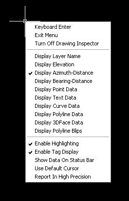
This command is available in any of the Civil Suite products (Survey, Civil, Hydrology, and GIS), or Takeoff.  It works in both software installed on the AutoCAD platform or the IntelliCAD platform.  By default, it will display the layer an object resides upon in the tooltip, but you can change the type of information shown using the right-click context menu.

The right-click context menu displays the options for the Drawing Inspector

When you are finished viewing information about your drawing objects, right-click and choose the Turn Off Drawing Inspector option.  You can also toggle the Drawing Inspector off using the Inquiry pull-down menu.
Originally posted on Carlson Connection by Felicia Provencal


Another Twist for World

I’d like to offer a few other arguments for the use of the DVIEW TWIST routines discussed in North Rotation: Using Twist Screen. The four Carlson DVIEW routines cited:

  • Standard – This option allows you to select a rotation angle using the mouse.
  • Line, Polyline or Text – This option allow you to select an object to set as a view baseline.  It is the most useful when trying to match views to objects such as property lines or road centerlines.
  • Surveyor – This option prompts for the manual entry of a bearing or azimuth for the rotation angle.
  • Restore Due North – This option returns the screen to the orientation where North is straight up.

fall right in line with remarks made by ESRI’s Brent Jones at the 2009 Carlson User Conference who said:

“GIS changes the whole domain for surveyors,” Jones added, “And surveyors need to be ready for what’s coming next — high accuracy GIS. The key is geo-referencing,” he said. “We can use our data to communicate to our world with greater precision over greater areas.”

In my opinion, a User Coordinate System (UCS, by its very definition), takes the data one step further away from being geo-referenced. There are those that would probably argue that having data in a World Coordinate System (WCS) and at assumed coordinates of something like 5000,5000,100 is no better than using a UCS to shift this same data to a proper geo-referenced coordinate system. From a holistic stand-point, I’d tend to agree. However, what sets the WCS vs. UCS argument apart is this simple statement:

All drawings must have a WCS yet not all drawings have a UCS.

When one considers the longevity of information represented in drawings created to this point in time and then reflects on how this information might also be used in the future, I feel it is important to model that information (and subsequently allow that information to be easily extracted) in a consistent and reliable fashion. A User Coordinate System is typically only understood and used by its creator which in turn, limits its use and subsequently increases the risk of liability when the User Coordinate System isn’t known or understood by a “downstream” recipient of the drawing (survey stake-out, machine control excavation, etc).

Side note observation… Is it me or are there some parallels between UCS and custom ARX objects used in other products? When I look at how long the DVIEW vs. UCS arguments have been made, I can only surmise the length of time that will be involved to bring the non-proprietary vs. proprietary data argument to a close. I suspect it’s going to be a long, tough road.

In any event, it is my opinion that standardizing on a single WCS should provide more consistent deliverables when the drawings/projects span multiple people, offices and/or disciplines. When properly adopted, using a “twisted view” of geo-referenced data in a World Coordinate System should provide more feature-rich information now and into the future when our data is mapped onto the Earth.

Originally posted on Carlson Connection by Ladd Nelson


Engineering, Construction, and BIM

There have been many articles, discussions, and presentations on Building Information Modeling in the recent months.  If you haven’t already heard the basics, this post covers it well.  For surveyors, civil engineers, and construction firms, there are two things you should know about BIM and how it will impact your business.

First, BIM is very similar in its goals and processes to GIS.  Basically, you are attaching data and other information to objects.  This allows you to manage the facilities after they have been built and track their contents over time. This is very similar to how as-builts of infrastructure are managed and tracked through a GIS system. Water and storm sewer sytems, telecomm transmission lines, and landscaping are types of things that are traditionally managed using GIS.  The information age has dramatically opened up opportunities for professionals to gather, collate, and attach data to their surveys, designs, and as-builts. 

Secondly, since buildings are not constructed in isolation, they must tie into the site grading and infrastructure, further opportunities for designers and contractors have opened up.  Complex site plans showing how the grading, structural design, and utilities will all connect are now possible, and represent a new deliverable for firms to offer their clients.  Carlson Software offers many solutions for creating these models and because Carlson data migrates well between various CAD and GIS platforms, owners and developers of these projects can be assured that their designs will be ready for management once construction is complete.

Originally posted on Carlson Connection by Felicia Provencal


Carlson + ESRI = Wow!


So, how cool is this? 

At the Carlson User Conference this week in Lexington, KY, Brent Jones of ESRI announced a new grant program in coordination with Carlson Software. The program will bring ESRI products to every IntelliCAD-based Carlson program.

Speaking with Brent on Tuesday, he said that a few of the details have yet to be worked out, but Carlson IntelliCAD users should be hearing details in about a month.

Originally posted on Carlson Connection by Jennifer Dibona


Brent Jones of ESRI discusses ‘Why GIS Needs Surveyors’

Combining all the GIS and land development technologies that exist today is what Brent Jones suggested surveyors do in his keynote address to the attendees at the 2nd annual Carlson User Conference. Jones, PE, PLS, is the Survey, Cadastre, and Engineering Industry Manager for ESRI, which designs and develops the world’s leading geographic information system (GIS) technology.

To help surveyors accomplish this, Jones announced an upcoming grant program to be offered by ESRI for every Carlson IntelliCAD user. “ESRI is very supportive of Carlson’s development on IntelliCAD and we want to support your users,” said Jones of this specialized grant program being developed exclusively for Carlson IntelliCAD users. “We want to help surveyors leverage their existing resources to help in the GIS market.”  With this offer Carlson IntelliCAD users will be able to access GIS technology and jump-start a GIS practice. Read More

Originally posted on Carlson Connection by Karen Cummings


Dewberry’s Dave Palumbo presents ‘Choosing and Implementing Carlson’

Starting his presentation at the Carlson User Conference by saying “Carlson works for us,” Dave Palumbo, PE, Technology Manager for Infrastructure Services at Dewberry, noted that Dewberry, an ENR top 50 design firm was an early adopter of technology as a differentiator. The evaluation and implementation of three competing solutions took Dewberry more than two years. “Patience was of the essense,“ Palumbo said.

Read the entire post

Originally posted on Carlson Connection by Karen Cummings


Carlson Software Expands Carlson College™

Carlson Software recently expanded their expert level training program, Carlson College™, and started the Carlson College Training Program. This new program will allow individuals and companies to get training direct from Carlson Software or through the members of the Carlson College Training Program. New members of the Training Program include Harken-Reidar Inc. of Front Royal, Va.; Carlson Desktop Solutions (CDS), based in Austin, Texas; That CAD Girl, located near Raleigh, N.C.; and, for C&G products only, Larry Phipps of the Land Surveyor’s Workshop in Jefferson, N.C. Membership in the Carlson College Training Program is available to any person or organization that makes a commitment to providing quality training on Carlson Software products.

For more information on the Carlson College Training Program or training, please contact Carlson Software at 800-989-5028, email training@carlsonsw.com or visit www.carlsonsw.com/training. Members of the Carlson College Training Program are independent entities from Carlson Software.

Read the entire Press release here.

Originally posted on Carlson Connection by Karen Cummings


Poll Question 3/30/2009

[polldaddy poll=1493826]

Originally posted on Carlson Connection by Jennifer Dibona


Large Companies DO Use Carlson – Dewberry Presenting Implementation Case Study at Conference

Carlson Software put out a press release this week announcing that a representative of Dewberry will be making a presentation at the User Conference about their recent implementation of Carlson Survey and Civil Software.

This is a good supporting argument for my Myth #7 about how large companies DO use Carlson.

Click here for the press release about Dewberry.

Originally posted on Carlson Connection by Jennifer Dibona


BIM this, BIM that… What is BIM?

 Q:     What is BIM? And, exactly how does it relate to the civil engineering industry?

 A:     BIM, by definition, has nothing to do with civil engineering.

BIM stands for “Building Information Modeling”. The term “BIM” originated in the Architectural world and, generally, defines the process of inputting information to and extracting information from a 3D model of a building/facility.

Definition of BIM from the National BIM Standard:

BIM is best thought of as “a digital representation of physical and functional characteristics of a facility…and a shared knowledge resource for information about a facility forming a reliable basis for decisions during its life-cycle; defined as existing from earliest conception to demolition.”

From the National Institute of Building Sciences:

Building Information Modeling (BIM) refers to the use of the concepts and practices of open and interoperable information exchanges, emerging technologies, new business structures and influencing the re-engineering of processes in ways that dramatically reduce multiple forms of waste in the building industry. The National BIM Standard, a key element of the overall industry transformation being supported and coordinated by the buildingSMART alliance™, establishes standard definitions for building information exchanges to support critical business decisions. Implemented in software, the consensus-based standard will form a basis for more accurate and efficient commerce within the capital facilities industry. The National BIM Standard is also intended to help participants in facilities-related processes achieve more reliable outcomes from commercial agreements.

From Geomatics International:

A Building Information Model (BIM) is a digital representation of physical and functional characteristics of a building. Construction and management of buildings involves many stakeholders, so that proper sharing of information over the entire lifecycle of a building is very important. The Open Geospatial Consortium (OGC) is developing BIM standards that promote efficient web-based information sharing in the Architectural, Engineering, Construction and building Ownership and Operation (AECOO) markets.

Because Wikipedia is open-source and able to be edited by anyone and everyone, the entry for BIM changes regularly. The entire entry looked like this as of February 26, 2009. Here is an excerpt:

Building Information Modeling (BIM) is the process of generating and managing building data during its life cycle[1]. Typically it uses three-dimensional, real-time, dynamic building modeling software to increase productivity in building design and construction.[2] The process produces the Building Information Model (also abbreviated BIM), which encompasses building geometry, spatial relationships, geographic information, and quantities and properties of building components.

A lot of confusion is now occurring because Autodesk and their civil resellers are trying to make the connection between BIM and Civil or, more specifically, Civil 3D. See examples here:

BIM for Civil Engineers by Sanjay Asnani, Autodesk
  If link doesn’t work, find this document HERE.

What Does BIM Mean for Civil Engineers? by Adam Strafaci, Autodesk

Civil 3D and BIM… How do they relate? by Melanie Santer, US CAD

However, if you simply Google “bim building information modeling” and look at the first two pages of returns, the only entries that attempt to connect BIM and civil engineering belong to Autodesk or one of their civil resellers. All other hits refer to BIM in an architectural/building sense. If there is a specific software program mentioned, it is Autodesk’s Revit product. A caveat to this is the civil/structural engineering specialty field of bridge construction which can also be modeled using Revit. Bridge construction is a bit of a hybrid in that it is similar to building design and can also legitimately be related to BIM.

Among Autodesk’s architectural team and resellers, most, if not all, references to BIM are solely in an architectural/building capacity. See examples here (pages were cached on 2/26/09):

Brave New BIM

The World According to BIM – Part 1

Summit AEC – Autodesk BIM & CAD Software

As you can see from the above links, it is technically incorrect to connect BIM and Civil. However, many in the civil world are witnessing the Autodesk definition of BIM take hold. So, in the event you are ever asked or required to “BIM” a civil project, you are essentially being asked to design and deliver a dynamic, 3d model of the entire project.

It is important to realize that creating a dynamic 3d model for a Civil project (or “BIM”ing a civil project) is not limited to using a particular software program.

Find a civil engineering design software that allows you to design to specific criteria, is able to show a great visual representation of all the components of your project in 3D view and is able to dynamically reflect changes and you can “BIM” along with the rest of the world.

Designing a project using a dynamic model allows you to design according to specific criteria such as AASHTO (American Association of State Highway and Transportation Officials) standards or by specifying minimum/maximum values for storm or sanitary sewer design. It also is invaluable to detect, before construction, potential conflicts between a proposed network of roads and associated utility networks. As an example, a dynamic 3d model would trigger a warning if, when lowering a roadway, the rule for minimum cover over a pipe on an adjacent roadway has been violated. Also, creating this model allows you to view the model, make changes to vertical alignments and see dynamically updated cut/fill quantities all at once.

To reduce the confusion, it might be time to coin a new term such as “Site Information Modeling” to describe the process in the Civil industry. But, there is still quite a disparity between the “Information Modeling” done for a Building compared to that done for a Civil project. In true BIM, the “I” (Information) component is as important as the “M” (Modeling) component because determining usability and functionality of the Building through its lifecycle is one of the goals of BIM. At this time, the process on the Civil side is still much more about the “Model” and not nearly so much about the “Information” going into and coming out of the model. When we are able to incorporate results of traffic flow analyses for a roadway or inspection reports showing sludge build-up and flow capacities in sewer/storm pipies and manholes, we will be truly using the “Information” as it was intended in an “Information Model”.

Originally posted on Carlson Connection by Jennifer Dibona

1 of 1